![]()
 Function Block
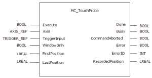
![]() A function block groups an algorithm and a set of private data. It has inputs and outputs. - Arms a Fast Input
A function block groups an algorithm and a set of private data. It has inputs and outputs. - Arms a Fast Input![]() The inputs are taken into account at each cycle depending on the system periodicity (for example each millisecond). Under certain circumstances this can be insufficient when more accuracy is needed, or if a quick response is required from the system. To fill the gap, a drive may have some Fast Input connections (generally one or two). When an event happens that triggers a Fast Input (e.g. when a sensor sends a rising edge), the detection of a signal occurs faster (which can be 1000 times more accurate than the system periodicity). Then the timestamp associated with this input can be provided to the IPC to take corrective action and returns the latched position when the Fast Input event occurs.
The inputs are taken into account at each cycle depending on the system periodicity (for example each millisecond). Under certain circumstances this can be insufficient when more accuracy is needed, or if a quick response is required from the system. To fill the gap, a drive may have some Fast Input connections (generally one or two). When an event happens that triggers a Fast Input (e.g. when a sensor sends a rising edge), the detection of a signal occurs faster (which can be 1000 times more accurate than the system periodicity). Then the timestamp associated with this input can be provided to the IPC to take corrective action and returns the latched position when the Fast Input event occurs.
Inputs
|
Input |
Data Type |
Range |
Unit |
Default |
Description |
|---|---|---|---|---|---|
|
Execute |
BOOL |
0, 1 |
N/A |
No default |
On the rising edge |
|
Axis |
AXIS_REF |
1, 256 |
N/A |
N/A |
Selects the axis the position is latched to. |
|
TriggerInput |
TRIGGER_REF |
See Description. |
N/A |
No default |
|
|
BOOL |
No range |
N/A |
No default |
Enables a position latching window.
|
|
|
FirstPosition |
LREAL |
No range |
User units |
No default |
See the WindowOnly Description about how this input and the LastPosition input define the window.
|
|
LastPosition |
LREAL |
No range |
User units |
No default |
See the WindowOnly Description about how this input and the FirstPosition input define the window.
|
Elements
This is the drive capture engine to be used.
INT TriggerInput.InputID
InputID INT
Range = 0, 1
- 0 = Touch Probe 1 / Capture Engine 0
- 1 = Touch Probe 2 / Capture Engine 1
This is the input signal’s edge to capture.
INT TriggerInput.Direction
Range = 1, 2
- 1 = Rising edge.
- 2 = Falling edge.
-
- Trigger Direction is also sent to the servo drive
 A servo drive is a special electric amplifier used to power electric servo motors. It monitors feedback signals from the motor and continually adjusts for deviation from expected behavior and is shown in the WorkBench Position Capture screen Edge setup.
This is where the input comes from.
INT TriggerInput.TrigID
Range = 0, 256.
0 = Trigger axis is to be the same as Axis.AXIS_NUM.
This is the capture method.
INT TriggerInput.TrigMode
Range = 0, 1
- 0 = Time based capture.
- 1 = Position based capture.
- For position based capture, the TrigID must be the same as the AXIS_REF.
-
- The Mode (either Time or Position) must be configured the same in the servo drive.
This can be done either in:- COE Init commands and executed when the EtherCAT
 ***EtherCAT is an open, high-performance Ethernet-based fieldbus system. The development goal of EtherCAT was to apply Ethernet to automation applications which require short data update times (also called cycle times) with low communication jitter (for synchronization purposes) and low hardware costs network is initialized (0x3460, subindex 3 and 4).
 - The WorkBench Positon Capture screen.
- COE Init commands and executed when the EtherCAT
Outputs
|
Output |
Data Type |
Range |
Unit |
Description |
|---|---|---|---|---|
|
Done |
BOOL |
|
|
|
|
Busy |
BOOL |
|
|
Indicates the specified input is:
|
|
CommandAborted |
BOOL |
|
|
Indicates the move was aborted. A TriggerAbort function block has executed and canceled this function. |
|
Error |
BOOL |
|
|
The function block has not completed successfully due to an error. The ErrorID output indicates the type of error. See PLCopen Function Block ErrorIDs for more information. |
|
ErrorID |
INT |
|
|
|
|
RecordedPosition |
LREAL |
|
User units |
|
Remarks
-
- This function block starts a motion-related action and stores data for calculations and error checking.
See Call Function Blocks Multiple Times in the Same Cycle if using a dual-core controller.
- This function or function block does not generate any motion.
- See Function Blocks - General Rules for more information about how inputs and outputs work.
- This function block captures an axis position
- When the Execute input transitions from low to high, the control requests the drive to arm its Fast Input to latch the axis position when a Fast Input occurs.
- The Axis input specifies which axis's position to latch and the TriggerInput input specifies which Fast Input to use and whether to trigger on the rising or falling edge of the Fast Input.
- When the Fast Input event occurs, the drive latches the axis's position.
- This function block then returns the latched position at the RecordedPosition output and set the Done output high.
- This process can be canceled with the AbortTrigger function block.
- If the WindowOnly input is high, the FirstPosition input and the LastPosition input define a window in which a Fast Input is accepted.
- Any Fast Input events that occur outside the window is ignored.
-
- There are differences in how MC_TouchProbe interacts with AKD and AKD2G drives.
See these topics for drive-specific information:
-
-
The accuracy of captured position data depends on the travel velocity. Please see the article MC_TouchProbe and Time-Based Capture on KDN for more information and how to correct for timing.
Example 1
If First Position ≤ LastPosition, the window in which a Fast Input is accepted is:
FastInputPosition ≥ FirstPosition AND FastInputPosition ≤ LastPosition
Example 2
If First Position > LastPosition, the window in which a Fast Input is accepted is:
FastInputPosition ≥ FirstPosition OR FastInputPosition ≤ LastPosition
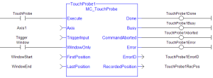
This image shows the ladder diagram view of the MC_TouchProbe function block:
Figure 6-213: MC_TouchProbe
Fast Homing - Inputs
See these topics for more information:
- Fast Homing Example with the Pipe Network Motion Engine Axis Pipe Block
- Fast Homing Example with the PLCopen Motion Engine
- Fast Inputs with Pipe Network Motion
- Pipe Network Registration and Fast Homing
- Registration Position Capture Example with Pipe Network Trigger Block
Usage
This function block can be used to:
- Perform registration
- Determine the position of a product
- Measure product length
Limitations
- Both high speed inputs cannot be used at the same time.
- The TrigMode option is only used by MC_TouchProbe.
FBD Language Example
Not available.
FFLD Language Example
IL Language Example
Not available.
ST Language Example
(* MC_TouchProbe ST example *) |
See Also


