 Function Block
![]() A function block groups an algorithm and a set of private data. It has inputs and outputs. - Performs a single-axis move to a specified endpoint position.
A function block groups an algorithm and a set of private data. It has inputs and outputs. - Performs a single-axis move to a specified endpoint position.
Inputs
|
Input |
Data Type |
Range |
Unit |
Default |
Description |
||||||||||||
|---|---|---|---|---|---|---|---|---|---|---|---|---|---|---|---|---|---|
|
Execute |
BOOL |
0, 1 |
N/A |
No default |
On the rising edge |
||||||||||||
|
Axis |
AXIS_REF |
1, 256 |
N/A |
No default |
Name of a declared instance of the AXIS_REF library function.
|
||||||||||||
|
Position |
LREAL |
See Description. |
User units |
No default |
Endpoint position.
|
||||||||||||
|
Velocity |
LREAL |
No range |
User unit/sec |
No default |
|||||||||||||
|
Acceleration |
LREAL |
No range |
User unit/sec2 |
No default |
Trapezoidal: Acceleration rate. S-curve: Maximum acceleration.
|
||||||||||||
|
Deceleration |
LREAL |
No range |
User unit/sec2 |
No default |
Trapezoidal: Deceleration rate. S-curve: Unused. See S-curve and Trapezoidal Acceleration / Deceleration for more information. |
||||||||||||
|
Jerk |
LREAL |
No range |
User unit/sec3 |
No default |
Trapezoidal: 0 (zero). S-curve: Constant jerk
|
||||||||||||
|
Direction |
SINT |
0, 4 |
N/A |
No default |
When Rollover Position is zero, a value of 0 must be specified. When Rollover Position is nonzero, a value of 1, 2, 3, or 4 must be specified.
If the Position input is the same as the axis's current position, then:
|
||||||||||||
|
BufferMode |
SINT |
0, 5 |
N/A |
No default |
|
Outputs
|
Output |
Data Type |
Range |
Unit |
Description |
|---|---|---|---|---|
|
Done |
BOOL |
No range |
N/A |
Indicates the move completed successfully. |
|
Busy |
BOOL |
No range |
N/A |
High from the moment the Execute input goes high until the time the move is ended. |
|
Active |
BOOL |
No range |
N/A |
Indicates this move is the Active move. |
|
CommandAborted |
BOOL |
No range |
N/A |
Indicates the move was aborted. |
|
Error |
BOOL |
No range |
N/A |
Indicates either:
|
|
ErrorID |
INT |
No range |
N/A |
Indicates the error if Error output is TRUE. See PLCopen Function Block ErrorIDs for more information. |
Remarks
-
- This function block starts a motion-related action and stores data for calculations and error checking.
See Call Function Blocks Multiple Times in the Same Cycle if using a dual-core controller.
See Main for more information about how this function is used in the Hole punch project.
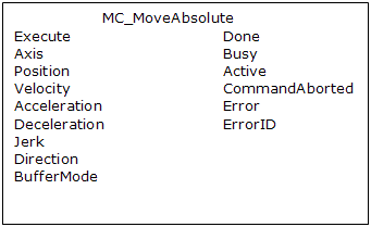
Figure 6-225: MC_MoveAbsolute
Time Diagram
These images show two examples of the combination of two absolute move Function Blocks (FBs):
- The left part of the diagram illustrates when the second FB is called after the first one.
- If the first reaches the commanded position of 6000, and the velocity is 0 (zero), the output Done causes the second FB to move to the position 10000.
- The right part of the diagram illustrates when the second move FB starts the execution while the first FB is still executing.
- The first motion is interrupted and aborted by the Test signal during the constant velocity of the first FB.
- The second FB moves directly to the position 10000 although the position of 6000 is not yet reached.
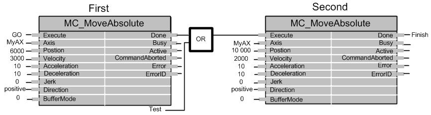
Figure 6-226: Time Diagrams: First and Second FBs
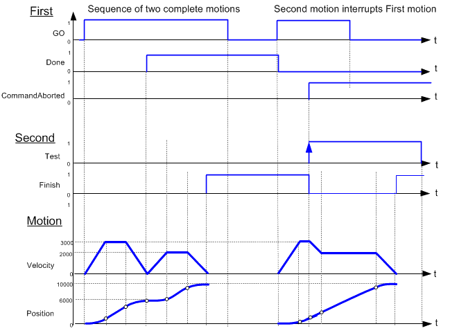
Figure 6-227: Time Diagram
FBD Language Example
Not available.
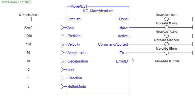
FFLD Language Example
IL Language Example
Not available.
ST Language Example
            (* MC_MoveAbsolute S
T example *)
Inst_MC_MoveAbsolute( MovAbsReq, Axis1, 1234.567, 100.0, 100.0, 100.0, 0, 0, 0 );  //instance of MC_MoveAbsolute
MovAbsDone := Inst_MC_MoveAbsolute.Done;  //store done output into user defined variable
MovAbsBusy := Inst_MC_MoveAbsolute.Busy;
MovAbsActive := Inst_MC_MoveAbsolute.Active;
MovAbsAborted := Inst_MC_MoveAbsolute.CommandAborted;
MovAbsError := Inst_MC_MoveAbsolute.Error;
MovAbsErrID := Inst_MC_MoveAbsolute.ErrorID;
See Also


