AKT2G-IO-SM-Lxx Stepper Drive Configuration tab
This tab is used to configure the device, based on the parameters of the stepper motor being used, and to diagnose any problems with the stepper terminal. To make configuration simple, a Kollmorgen stepper motor can be selected from the Properties tab, which automatically populates the stepper motor parameter fields.
The stepper motor parameters can also be replicated to a file and transferred between devices. Once the project is compiled, the CoE Init Commands tab is populated based on these values.
Troubleshooting the stepper terminal can begin by gathering information from the Diagnostics tab.
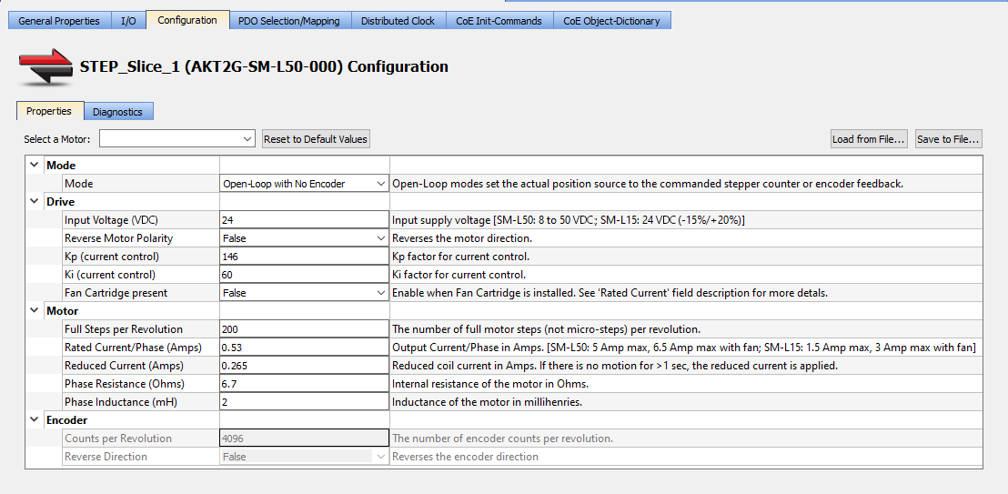
Properties tab
|
Select a Motor |
The drop-down list contains the Kollmorgen stepper motor models and their specific parameters.
|
|
Reset to Default Values |
Click this button to change all of the stepper motor parameters to their default values. |
|
Load from File... |
Click this button to select an XML |
|
Save to File... |
Click this button to create an XML file containing all of the current stepper parameters. This file can be stored or transferred between devices. |
| Section | Element | Description |
|---|---|---|
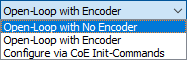
| Mode | Mode | Select the CoE object used for the actual position.
|
| Drive | Input Voltage (VDC) |
Specify the input supply voltage. The range is:
|
| Reverse Motor Polarity |
Select True or False from the drop-down menu to reverse the motor direction. |
|
| Speed Range |
Select the maximum output full-step frequency from the drop-down list. |
|
| Kp (current control) |
Specify the proportional gain factor for current control. |
|
| Ki (current control) |
Specify the integral gain factor for current control. |
|
| Fan Cartridge Present |
Set this to True if a AKT2G-AC-FAN-001 fan cartridge is installed. Having a fan present allows you to set the Rated Current / Phase (Amps) to a higher value. |
|
| Motor | Full Steps per Revolution |
Specify the number of full motor steps per revolution. |
| Rated Current / Phase (Amps) |
Specify the motor’s rated current per phase in Amps.
Maximum Motor Current/Phase (RMS) Values
Maximum Converted Peak Output Values
|
|
| Reduced Current/Phase (Amps) |
Specify the motor’s current per phase in Amps when at standstill.
|
|
| Phase Resistance (Ohms) |
Specify the internal resistance of the motor in Ohms. |
|
| Phase Inductance (mH) |
Specify the motor's inductance in millihenries. |
|
| Encoder | Counts per Revolution |
Specify the number of encoder counts per revolution. |
| Reverse Direction |
Select True or False from the drop-down menu to reverse the encoder direction. |
-
-
- See Add and Configure I/O Slices for adding a stepper drive to your project.
- See AKT2G-SM-L15-000 or AKT2G-SM-L50-000 for information on the devices.
- See AKT2G-SM-Lx Object Description for stepper drive-specific object descriptions.
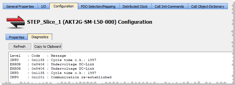
Diagnostics tab
This tab gathers the diagnostic messages available on the connected stepper terminal.
- This information can be used for troubleshooting during commissioning or operation.
- The PLC
 "Programmable Logic Controller"
A Programmable Logic Controller, PLC, or Programmable Controller is a digital computer used for automation of industrial processes, such as control of machinery on factory assembly lines.
Used to synchronize the flow of inputs from (physical) sensors and events with the flow of outputs to actuators and events application must be running on a controller or Online Configuration mode must be enabled to acquire diagnostics data.
"Programmable Logic Controller"
A Programmable Logic Controller, PLC, or Programmable Controller is a digital computer used for automation of industrial processes, such as control of machinery on factory assembly lines.
Used to synchronize the flow of inputs from (physical) sensors and events with the flow of outputs to actuators and events application must be running on a controller or Online Configuration mode must be enabled to acquire diagnostics data.
|
Refresh |
Click this button to read and view the stepper terminal's messages. See AKT2G-SM-Lxx Diagnostic Messages for a comprehensive list of messages. This button is disabled under these conditions.
|
|
Copy to Clipboard |
Click this button to copy the message data. |
- Connect to your controller.

- Compile and download the application.

- Enable Online Configuration Mode.

- OR -
Start the application.


