Map I/O from the Project Explorer
-
- For information on mapping I/O with third-party devices, see the PDO Selection/Mapping tab.
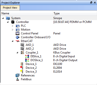
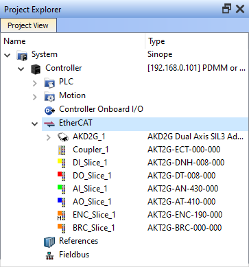
- In the Project Explorer, expand the Controller node and the EtherCAT
 ***EtherCAT is an open, high-performance Ethernet-based fieldbus system. The development goal of EtherCAT was to apply Ethernet to automation applications which require short data update times (also called cycle times) with low communication jitter (for synchronization purposes) and low hardware costs nodes to access your devices.
 - Accessing the device properties is slightly different depending upon the device.
- AKD or AKD2G
- Controller
- I/O Slice
- Safety Slices
- There are several ways to map variables:
- Drag and drop a variable from the Dictionary onto a table entry.
- Use the PLC Variable Creation Wizard for Kollmorgen devices.
- Directly map/unmap the Inputs/Outputs to PLC variables using the PLC Variable Selector.
-
- The Unmap command in the contextual menu is used to remove the link between the variable and the associated channel(s).
In addition, deleting a variable from the dictionary which is mapped to the channel(s) also removes the link(s). The list of variables is filtered to display only those with relevant types.
- PLC Variable Selector displays Read Only variables when mapping the Input channels from the I/O tab.
- Variables assigned to the Safe Digital Input and Safe Digital Output channels must be Read Only.
|
|
| AKT (K-Bus) devices | AKT2G (E-Bus) devices |
For AKD and AKD2G devices, double-click the drive in the project tree and select the I/O tab.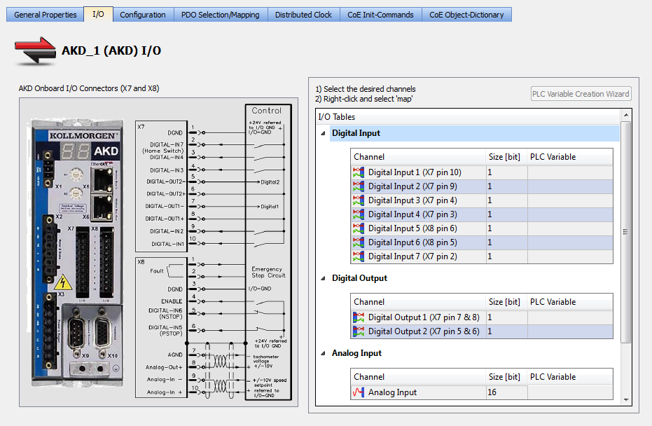
For KAS controllers, double-click Controller Onboard I/O in the project tree.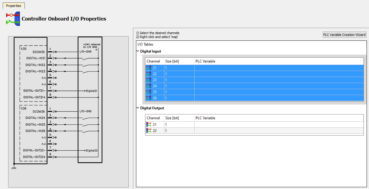
For I/O slices, double-click the I/O Slice under EtherCAT (AKT2G) or the Coupler entry (AKT) in the project tree. Then click the I/O tab.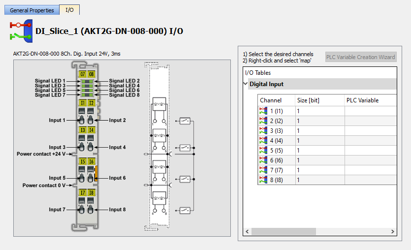
For Slice Analog I/O and thermocouples, the offset and gain parameters must be defined. 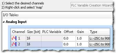
For safety devices, double-click the Safety I/O Slice under EtherCAT in the project tree and click the I/O tab.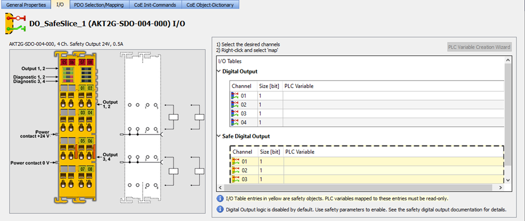
Digital output logic on the safety slices / devices is typically disabled by default from the standard PLC![]() "Programmable Logic Controller"
A Programmable Logic Controller, PLC, or Programmable Controller is a digital computer used for automation of industrial processes, such as control of machinery on factory assembly lines.
Used to synchronize the flow of inputs from (physical) sensors and events with the flow of outputs to actuators and events.
"Programmable Logic Controller"
A Programmable Logic Controller, PLC, or Programmable Controller is a digital computer used for automation of industrial processes, such as control of machinery on factory assembly lines.
Used to synchronize the flow of inputs from (physical) sensors and events with the flow of outputs to actuators and events.
See the Description of Safety Parameters and the AKT2G-SDO-004-000 Safety Terminal with Four Digital Fail-safe Outputs table for details.
Select the channel(s) to map. Selection may be done by click-dragging or shift-clicking a range of entries. The entire table may be selected by clicking on its border.
After the selection is made, right-click and select Map or press the Enter key.
This opens the PLC Variable Selector. 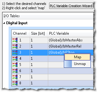
Choose the variable to be linked to the channel(s) or PDO object.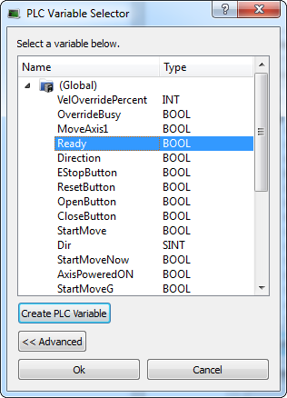
-
-
The limitations of PLC variable mapping are:
- Each PLC variable can be mapped to an EtherCAT I/O and exclusively to either:
- a Controller Onboard I/O.
- an external driver.
- Because a variable can only be mapped to one channel or PDO object, when you link a variable to a new channel or PDO object, the previous mapping is removed (even if linked to another slice or device).
- Individual bits within a variable can be mapped to multiple I/O channels on different devices (AKD, AKD PDMM, PCMM, or Slice).
Example: The same PLC variable cannot be mapped to both Profinet and a Controller Onboard I/O but it is possible with a regular EtherCAT I/O.
- Each PLC variable can be mapped to an EtherCAT I/O and exclusively to either:
When a device is removed using ECATDeviceAction:
- Variable mapped to an Analog or Digital Input Type
- The value of the variable becomes '0' when the mapped device is removed.
- The device I/O value is automatically reconnected to the variable when the device is reconnected to the network.
- Variable mapped to an Analog or Digital Output
- The value is not sent to the device when the mapped device is removed.
- When the device is reconnected, the value is sent to the I/O automatically.
All of the I/Os mapped to the X22 connector are grayed out in the IO tab:
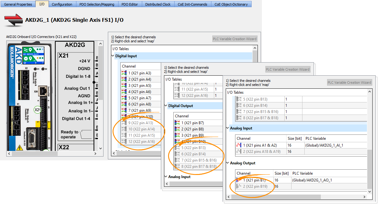
-
-
AKD2G drives are available with various I/O options.
An AKD2G drive of one variant can be replaced in the KAS project with a drive that has a different I/O option.
See the AKD2G Model Nomenclature section in Automation and Motion Control Programmable Automation Solutions for available models and I/O options.
See Also:
- PLC Variable Selector for information about the Create PLC Variable and Advanced buttons.
- Analog I/O Parameters for information about parameters.
- Configure Onboard I/O for information about the AKD Onboard EtherCAT I/Os.
- Controller Onboard I/O for information about the AKD PDMM or PCMM local digital I/Os.


