Overview
The encoder emulation (EEO) connector (X9) can be used as either an output or an input. As an output, you can use this connector for position feedback to an analog controller and for configuring the drive as the master in a master/slave system. You can also use X9 connector as an input for controlling the drive through an A/B, pulse and direction, or CW/CCW command. Common applications for this input include using the drive with a stepper controller and configuring the drive as the slave in a master/slave system.
Using Encoder Emulation
You can configure the X9 connector from the Encoder Emulation screen by setting the connector function, resolution, and (where applicable) input position. The Electronic Gearing screen also has provisions for setting the function of the X9 connector.
Function Settings
Function![]() A function calculates a result according to the current value of its inputs. A function has no internal data and is not linked to declared instances. settings for the X9 connector are assigned through the DRV.EMUEMODE parameter.
A function calculates a result according to the current value of its inputs. A function has no internal data and is not linked to declared instances. settings for the X9 connector are assigned through the DRV.EMUEMODE parameter.
Emulation Mode
0-Input (No EEO Output). While in Emulation Mode, the EEO connector (X9) is configured as an input. This is the recommended setting and should be used in coordination with FB2.MODE to select the type of inputs the secondary feedback will accept. See Feedback 2 (FB2 Parameters) for definitions for the EEO Connector (X9). Note that this mode is also deprecated and will behave as it did with firmware versions prior to M_01-03-00-000.
In earlier firmware versions, this mode indicates that the EEO connector is not operative.
Output Modes 1, 2, 6, 7, 8 and 9
The drive generates ouput pulses based on the motor position. Pulse![]() When the step gets activated, the action is activated for a single execution, and possibly once again when the step is deactivated outputs on the SubD connector X9 are three signals: A, B and index, with 90° phase difference (i.e. in quadrature, hence the alternative term “A quad B” output), with a zero pulse.
When the step gets activated, the action is activated for a single execution, and possibly once again when the step is deactivated outputs on the SubD connector X9 are three signals: A, B and index, with 90° phase difference (i.e. in quadrature, hence the alternative term “A quad B” output), with a zero pulse.
If you are using the AKD as a master, the slave drives use the master's encoder output signals as command input and follows these commands (velocity and direction). The drives operate from an internal supply voltage.
Mode 1– A quad B with once per revolution index pulse
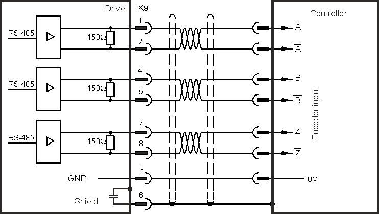
Output Mode 1 - A quad B with Once per Rev Index Pulse Connection Diagram
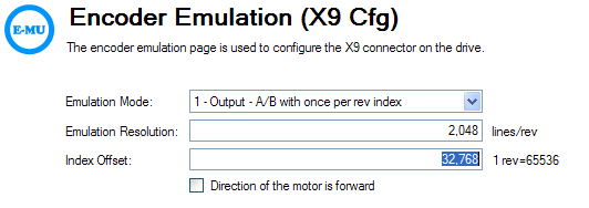
This output mode simulates an encoder signal from the X9 port to another AKD or external controller. EEO resolution (DRV.EMUERES ) defines how many counts are output for one revolution of the primary feedback.
Index offset (DRV.EMUEZOFFSET ) determines the point during the revolution of the primary feedback when the index pulse (X9 pins 7&8) is output through the X9 port. The pulse will occur once every revolution of the primary feedback is at the positive value of the offset. Notice that the offset's resolution is set based on 1 revolution = 65536, or a 16-bit scale. This is fixed and independent of the Resolution setting of the A and B channel above.

In this case, the Index is offset 180 degrees, or halfway through the revolution of the primary feedback.
Mode 2 – A quad B with absolute index pulse
Output Mode 2 - A quad B with Absolute Index Pulse Connection Diagram
When mode 2 is chosen, a box will appear for an absolute index point to be entered (DRV.EMUEMTURN ). The absolute index pulse will be output when the motor position reaches the full offset. The sum of the Absolute Offset (the revolutions) and the Index Offset (a fraction of a revolution) make up the "Full Offset". The index offset is fixed as 1rev = 65536, which is a 16-bit scale.
The "Full Offset" is a read-only calculation provided for easier understanding of the placement of the index pulse.
Mode 6 – Output - with once per revolution index and Input - Step and Direction
This mode allows you to output step and direction emulated encoder signals from the X9 (Emulated Encoder) connector, and input a step handwheel signal into the X7 (High Speed Opto IO) connector simultaneously. Mode 6 and 7 are identical, with the exception that the emulated encoder has an incremental Z pulse (Z pulse occurs every revolution) in mode 6, and an absolute Z pulse (Z pulse occurs at one absolute position) in mode 7. DRV.EMUERES, DRV.EMUEZOFFSET, and DRV.EMUETURN effect the position of the Z pulse for mode 6 in the same way as for mode 1.
Mode 7 – Output - with absolute Index and Input - Step and Direction
This mode allows you to output step and direction emulated encoder signals from the X9 (Emulated Encoder) connector, and input a step handwheel signal into the X7 (High Speed Opto IO) connector simultaneously. Mode 6 and 7 are identical, with the exception that the emulated encoder has an incremental Z pulse (Z pulse occurs every revolution) in mode 6, and an absolute Z pulse (Z pulse occurs at one absolute position) in mode 7. DRV.EMUERES, DRV.EMUEZOFFSET, and DRV.EMUETURN effect the position of the Z pulse for mode 7 in the same way as for mode 2.
Mode 8 – Output - with once per revolution index and Input - Clockwise/Counterclockwise pulse
This mode allows you to output CW/CCW emulated encoder signals from the X9 (Emulated Encoder) connector, and input a step handwheel signal into the X7 (High Speed Opto IO) connector simultaneously. Mode 8 and 9 are identical, with the exception that the emulated encoder has an incremental Z pulse (Z pulse occurs every revolution) in mode 8, and an absolute Z pulse (Z pulse occurs at one absolute position) in mode 9. DRV.EMUERES, DRV.EMUEZOFFSET, and DRV.EMUEMTURN affect the position of the Z pulse for mode 8 in the same way as for mode 1.
Mode 9 – Output - with absolute Index and Input - Clockwise/Counterclockwise pulse
This mode allows you to output CW/CCW emulated encoder signals from the X9 (Emulated Encoder) connector, and input a step handwheel signal into the X7 (High Speed Opto IO) connector simultaneously. Mode 8 and 9 are identical, with the exception that the emulated encoder has an incremental Z pulse (Z pulse occurs every revolution) in mode 8, and an absolute Z pulse (Z pulse occurs at one absolute position) in mode 9. DRV.EMUERES, DRV.EMUEZOFFSET, and DRV.EMUEMTURN affect the position of the Z pulse for mode 9 in the same way as for mode 2.
Input Modes 3, 4, and 5 (deprecated)
The X9 connector is capable of input modes. These input modes correspond to the signal types described below. The screen also includes provisions for setting the function of the X9 connector for input modes. Because these modes are deprecated and no longer available from the emulated encoder view, it is recommended to set DRV.EMUEMODE to 0 and use FB2.MODE to select the type of inputs the secondary feedback will accept.
Mode 3-A quad B signals
Input mode 3 allows an A quad B encoder or the encoder emulation output of another drive to be connected and used as a commander encoder, dual loop feedback, gearing, or camming input.
Mode 4-Pulse/direction signals
Input mode 4 allows the drive to be connected to a third-party stepper-motor controller. The number of steps can be adjusted so that the drive can be adapted to match the step-direction signals of any stepper controller.
Mode 5-CW/CCW signals
The drive can be connected to a third-party controller which delivers up-down signals.
Mode 10, Configure X9 for General Purpose I/O
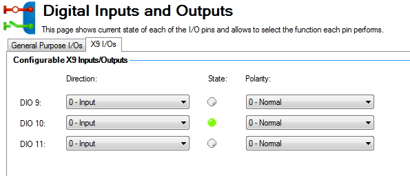
This mode allows the X9 connector's three transceivers to be used as general purpose inputs or outputs (DIO 9, 10, 11). DIOx.DIR is used to configure the transceivers as inputs or outputs. DIOx.INV controls the polarity of these signals.


Mode 11, Configure X9 for Endat 2.2
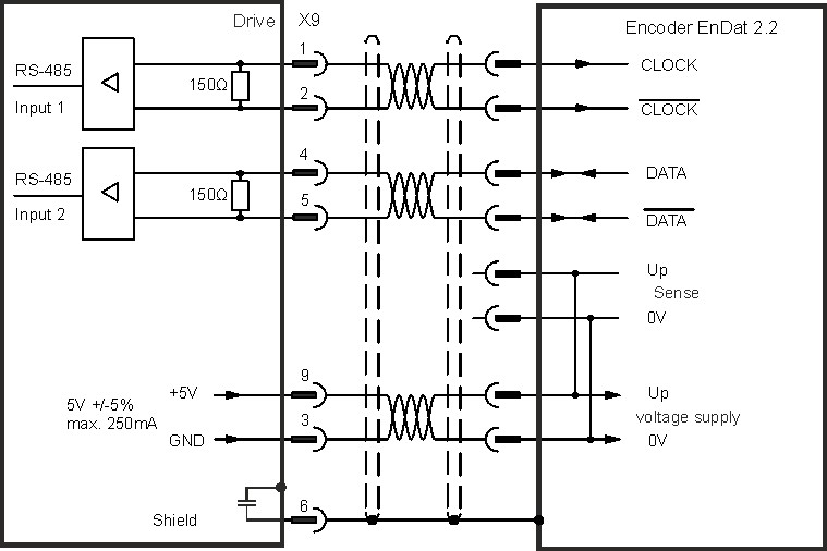
This mode allows a Heidenhain Endat 2,2 encoder to be connected to the drive through the X9 connector. This encoder can be used for primary feedback or handwheel input.

Output Modes 12, 13, and 14, Emulated Encoder Output with Z Pass Through
These modes are similar to modes 1, 6, and 8 respectively. They produce A/B (mode 12), Step/Direction (Mode 13), or CW/CCW pulses (Mode 14). The difference for these modes is the Z pulse follows the level of the feedback 1 index pulse. It is at a fixed position relative to the EEO input, rather than the EEO output.
-
-
If you are using multi-turn or single turn absolute feedback devices, and the once per revolution or absolute Z pulse modes (DRV.EMUEMODES 1,2,6,7,8, or 9) the Z pulse generated by the EEO will always be aligned with the same mechanical position of the primary feedback position. If you are using an incremental feedback device
 A process whereby some proportion of the output signal of a system is passed (fed back) to the input.
In automation, a device coupled to each motor to provide indication of the motor's shaft angle, for use in commutating the motor and controlling its speed and position and these modes, then the origin of the primary feedback is not at the same mechanical position each time the drive powers up. If you are using the pass through mode (DRV.EMUEMODES 12, 13, or 14) the Z pulse generated by the EEO will always be aligned with the same mechanical position of the primary feedback position.
-
- When using a multi-speed (greater than 2 pole) resolver as motor feedback, the AKDEEO will create only 1 Z pulse per each mechanical revolution of the motor. The Z pulse is dependent on the motor's starting location.
Output Modes 15, 16, and 17, Stepper Control Over Fieldbus
These modes are similar to modes 1, 6, and 8 respectively. They produce A/B (mode 15), Step/Direction (Mode 16), or CW/CCW pulses (Mode 17). No Z pulse is produced for these modes. The output is from an internal source in the drive that interpolates commands from the EtherCAT![]() ***EtherCAT is an open, high-performance Ethernet-based fieldbus system. The development goal of EtherCAT was to apply Ethernet to automation applications which require short data update times (also called cycle times) with low communication jitter (for synchronization purposes) and low hardware costs or CAN
***EtherCAT is an open, high-performance Ethernet-based fieldbus system. The development goal of EtherCAT was to apply Ethernet to automation applications which require short data update times (also called cycle times) with low communication jitter (for synchronization purposes) and low hardware costs or CAN![]() "Controller area network"
CAN is a broadcast, differential serial bus standard developed for connecting electronic control units. Each node is able to send and receive messages, but not simultaneously fieldbus networks.
"Controller area network"
CAN is a broadcast, differential serial bus standard developed for connecting electronic control units. Each node is able to send and receive messages, but not simultaneously fieldbus networks.
See Stepper Control and EEOs over fieldbus for examples.
Resolution
The resolution setting defines how many counts are output for one revolution of the primary feedback (when X9 is configured as an output), or how many counts will be considered a full revolution of the input signal from an external controller (when X9 is configured as an input). The resolution value is post-quadrature; for example, a 1,000 count encoder has a resolution of 4,000 counts.
Note: If the resolution value is set to 0, then the X9 connector will not produce a command.
Related Parameters and Commands
The DRV.EMUEMODE parameter sets the EEO output and input modes. The resolution (before multiplication) is set by the DRV.EMUERES function. The DRV.EMUEZOFFSET parameter adjusts and saves the zero pulse position within one mechanical turn. DRV.EMUEMTURN sets the absolute index point in mode 2 and DRV.HANDWHEEL sets the position at which the index pulse is output in output mode 2.


