![]()
 Function Block - Facilitates dancer and tension control in an electronic geared master/slave machine design.
Inputs
|
Input |
Data Type |
Range |
Unit |
Default |
Description |
|---|---|---|---|---|---|
|
Enable |
BOOL |
0, 1 |
N/A |
No default |
Enables execution. |
|
MasterID |
AXIS_REF |
N/A |
N/A |
No default |
Master axis identifier. |
|
SlaveID |
AXIS_REF |
N/A |
N/A |
No default |
Slave axis identifier. |
|
RatioNumerator |
DINT |
-2147483648 to 2147483647 |
N/A |
No default |
Numerator of master/slave ratio. |
|
RatioDenominator |
DINT |
-2147483648 to 2147483647 |
N/A |
No default |
Denominator of master/slave ratio. |
|
Acceleration |
LREAL |
-1.7E308 to 1.7E308 |
N/A |
No default |
Trapezoidal: Acceleration rate.
|
|
Deceleration |
LREAL |
-1.7E308 to 1.7E308 |
N/A |
No default |
Trapezoidal: Deceleration rate.
|
|
Jerk |
LREAL |
-1.7E308 to 1.7E308 |
N/A |
No default |
Trapezoidal: 0 (zero).
|
|
Kp |
LREAL |
-1.7E308 to 1.7E308 |
N/A |
No default |
Proportional gain. 14 to 15 significant digits of accuracy. |
|
Ti |
LREAL |
-1.7E308 to 1.7E308 |
N/A |
No default |
Integral gain. 14 to 15 significant digits of accuracy. |
|
Td |
LREAL |
-1.7E308 to 1.7E308 |
N/A |
No default |
Derivative gain. 14 to 15 significant digits of accuracy. |
|
DeviceFBValue |
DINT |
-2147483648 to 2147483647 |
N/A |
No default |
Analog input. |
|
DeviceSetPoint |
DINT |
-2147483648 to 2147483647 |
N/A |
No default |
Analog set point. |
|
ErrorDB |
LREAL |
-1.7E308 to 1.7E308 |
N/A |
No default |
Maximum or minimum error between DeviceFBValue and DeviceSetPoint before a change takes place. 14 to 15 significant digits of accuracy. |
|
RatioLimitPercent |
LREAL |
-1.7E308 to 1.7E308 |
N/A |
No default |
Maximum and minimum master/slave ratio window. 14 to 15 significant digits of accuracy. |
|
ErrorCalcMode |
BOOL |
0, 1 |
N/A |
No default |
|
Outputs
|
Output |
Data Type |
Range |
Unit |
Description |
|---|---|---|---|---|
|
OK |
BOOL |
0, 1 |
N/A |
The output has power flow after the enable input has been energized. |
|
NewRatio |
REAL |
-3.4E38 to 3.4E38 |
N/A |
New master/slave ratio. 6 to 7 significant digits of accuracy. |
|
Error |
BOOL |
0, 1 |
N/A |
Function block error. |
|
ErrorID |
INT |
-32768 to +32767 |
N/A |
Function block error value. |
Remarks
- This facilitation is done by using the analog feedback from an LVDT, tension transducer, potentiometer, encoder, resolver or some other similar device.
- The analog feedback value is compared to a pre-determined analog set-point.
- The difference or error is used in a PID algorithm with the summed output driving changes to the master/slave gearing relationship.
- This results in the slave axis either speeding up or slowing down to maintain desired tension.
This image shows the function or function block I/O.
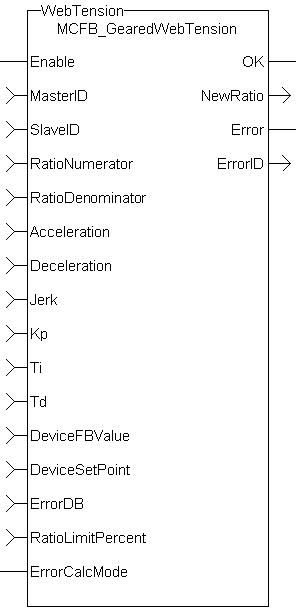
Figure 1: MCFB_GearedWebTension
Usage
- This UDFB is used in conjunction with the main ladder MC_GearIn function.
- It is assumed that the master/slave move is active.
- Internal to the UDFB is another call to the MC_GearIn function.
- Therefore, the MasterID, SlaveID, RatioNumerator, RatioDenominator, Acceleration, Deceleration, and Jerk inputs are the same values as the main ladder MC_GearIn function input values, both with the Buffer input of 0 (zero).
- This assures that the initial starting master/slave ratio will transition to the new Kollmorgen UDFB ratio smoothly.
- This UDFB changes the master/slave ratio defined by the MC_GearIn function based on the error between the analog input and the analog set-point.
- The magnitude of the ratio and the rate of the ratio change is defined by the Kp, Ti, Td PID gain values.
- The new ratio calculated is output at the NewRatio output.
- The RatioLimitPercent input is the maximum and minimum theoretical new ratio that can be changed.
- This provides a +/- window limit around the running ratio to prevent unwanted motion in the event of a web break or analog feedback failure.
Example 1
-
-
This example assumes the analog feedback device is located after (or downstream in the process) the feedroll axis.
RatioNumerator = 1
RatioDenominator = 2     Therefore the master/slave starting ratio is 0.5000000
ErrorCaclMode = 0
DeviceFBValue = 6
DeviceSetPoint = 4    Therefore error 6 – 4 = 2
Kp = 0.005
Ti = 0
Td= 0
From the equation:
New RatioDenominator = (RatioDenominator - Kp * error)
- The new RatioDenominator = (2 - 0.005*2) = 1.99.
- The new master/slave running ratio is 1 / 1.99 = 0.502512562.
- Since the master/slave ratio is greater than the previous ratio, the slave axis is going faster and the tension is reduced.
Example 2
-
-
This example assumes the analog feedback device is located before (or upstream in the process) the feedroll axis.
RatioNumerator = 1
RatioDenominator = 2     Therefore the master/slave starting ratio is 0.5000000
ErrorCaclMode = 1
DeviceFBValue = 6
DeviceSetPoint = 4    Therefore error is 4 – 6 = -2
Kp = 0.005
Ti = 0
Td= 0
From the equation:
New RatioDenominator = (RatioDenominator – (Kp * error))
- The new RatioDenominator = (2 + 0.005*2) = 2.01.
- The new master/slave running ratio is 1 / 2.01 = 0.497512437.
- Since the master/slave ratio is less than the previous ratio, the slave axis is going slower and the tension is reduced.
PID Function in KAS
There is a PID function in KAS that could be used for the PID control section in the UDFB.
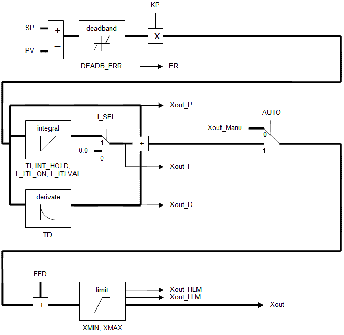
Figure 2: PID Function
Programming Tips
- The FB_FirstOrderDigitalFilter UDFB can be used to decrease excess dither on the analog input.
- The filtered analog value is then used at the DeviceFBValue input of the MCFB_GearedWebTension UDFB.
- The assumption is an MC_GearIn function block is first called in the main ladder and these initial values are used at the inputs for the UDFB.
- The resolution of the initial MC_GearIn the RatioNumerator and RatioDenominator inputs are directly related to the resolution of the calculated master/slave ratio (from the UDFB inputs) and may need to be scaled accordingly.
Example 1
- No scaling
Initial MC_GearIn input RatioNumerator = 2.
Initial MC_GearIn input RatioDenominator = 1 then initial Master/Slave ratio = 2. - UDFB input RatioNumerator = 2.
UDFB input RatioDenominator = 1 then UDFB Master/Slave ratio = 2. - UDFB input DeviceFBValue = 4.
UDFB input DeviceFBSetpoint = 3 then Device PID error = 1 assume KP = 1, Ti and Td =0. - New UDFB RatioNumerator = Current RatioNumerator – PID error = 2 – 1 = 1 then new UDFB Master/Slave ratio = 1.
Resolution = Master/Slave ratio:PID Error ratio = 1:1.
- The resolution is so coarse that a change of 1 for the error output of the PID creates a Master/Slave ratio change of 1.
- This result is a significant change to the slave velocity that will probably cause excess slack or web breakage.
Example 2
- Scaling value = 1000
Initial MC_GearIn input RatioNumerator = 2.
Initial MC_GearIn input RatioDenominator = 1 then initial Master/Slave ratio = 2. - UDFB input RatioNumerator = 2000
UDFB input RatioDenominator = 1000 then UDFB Master/Slave ratio = 2. - UDFB input DeviceFBValue = 4.
UDFB input DeviceFBSetpoint = 3 then Device PID error = 1 assume KP = 1, Ti and Td =0. - New UDFB RatioNumerator = Current RatioNumerator – PID error = 2000– 1 =1999 then new UDFB Master/Slave ratio = 1999.
Resolution = Master/Slave ratio: PID Error ratio = 2000:1.
- This resolution is much finer than Example 1.
- For a change of 1 for the error output of the PID this creates a Master/Slave ratio change of 1999.
- This results is a slower rate of change to the slave velocity that is more suited to good tension in a machine process.
FBD Language Example
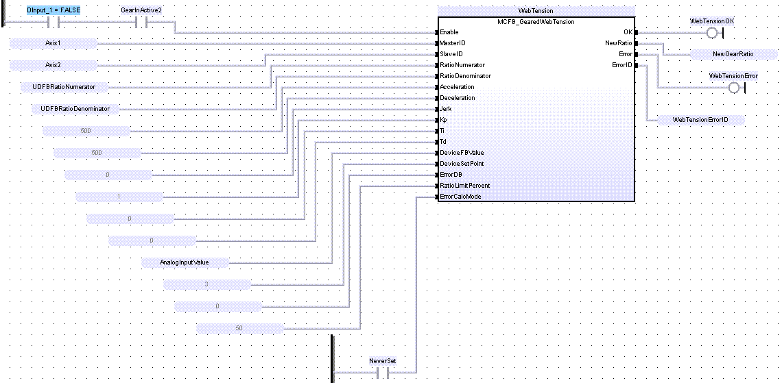
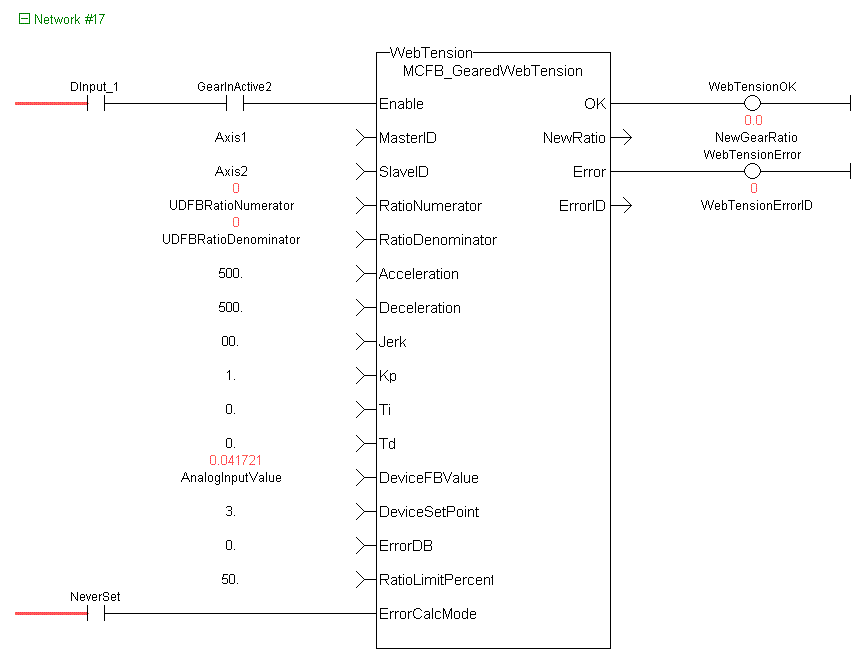
FFLD Language Example
IL Language Example
Not available.
ST Language Example
Inst_MCFB_GearedWebTension( DInput_1, Axis1, Axis2,
    ratioNumerator, ratioDenominator, 500.0, 500.0, 0.0, 1.0, 0.0, 0.0,
    AnalogInputValue, 3.0, 0.0, 50.0, NeverSet);
WebTensionOK       := Inst_MCFB_GearedWebTension.OK;
NewGearRatio       := Inst_MCFB_GearedWebTension.NewRatio;
WebTensionHasError := Inst_MCFB_GearedWebTension.Error;
WebTensionErrorID  := Inst_MCFB_GearedWebTension.ErrorID;
See Also


