Create a Linear or Circular Coordinated Motion Application
A Coordinated Motion application can be created in one of these ways:
- Use a Coordinated Motion template to create a new application.
- Two Coordinated Motion templates are currently available.
- The first template controls two PLCopen axes in coordinated motion.
- The second template controls two PLCopen axes in coordinated motion plus a third independent Pipe Network axis.
- Two Coordinated Motion templates are currently available.
- Modify an existing application to included coordinated motion functions.
- When modifying an existing application, axes need to be grouped to define the axes that will be active when performing coordinated motion on that group.
- See What are Axes Groups?.
-
-
Coordinated motion can only be performed with PLCopen axes.
Pipe Network axes do not support this feature.
Pipe Network axes can be moved independently from coordinated motion groups.
Any synchronization between coordinated motion and Pipe Network axes must be performed by the PLC application.
Groups
- Related axes are grouped in an axes group.
- Coordinated motion is then performed on an axes group.
- See What are Axes Groups?.
-
-
Remember these vital concepts when making interpolated motion.
- Interpolated motion requires creating a motion group that results in a second group coordinate system.
- Group coordinate system positions are only affected by group motion.
- Non-group coordinate system positions are only affected by non-group motion.
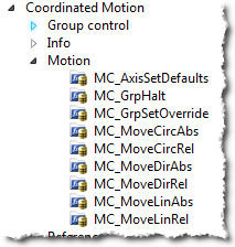
Group motion commands
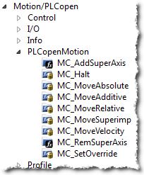
Non-Group motion commands
-
-
Axes that become part of a motion group are first homed using non –group function blocks to establish a home or starting position for the group motion.
Function Block Calls
These function blocks should be called before executing coordinated motion.
-
Call MLMotionInit (BasePeriod) to initialize the motion engine.
Base period is specified in microseconds.MLMotionInit(1000.0); // 1000 µSec -> 1 mSec
-
Call MC_CreateAxesGrp (Enable, GroupName, UpdateRate, MaxNumberOfAxes, AxesGroupRef) to create a Coordinated Motion Axes Group.
-
-
MC_CreateAxesGrp must be called between MLMotionInit() and MLMotionStart().
Inst_MC_CreateAxesGrp(TRUE, 'GROUP1', 6, 2, Group1_ref);
In this example, the axes group name is GROUP1, the update rate is 1 mSec (specified by '6') and the maximum number of axes that can be added to the group is 2.
The group reference variable Group1_ref is used in future coordinated motion function block calls to reference this newly created group. -
-
Call MC_InitAxesGrp (Enable, AxesGroup, VelLimit, AccLimit, DecLimit, JerkLimit) to initialize the path limits for velocity, acceleration, deceleration, and jerk.
Inst_MC_InitAxesGrp(TRUE, Group1_ref, 100.0, 300.0, 300.0, 1000.0);
In this example, the kinematic limits for axes group Group1_ref is set.
The velocity limit is set to 100.0 user units/second.
Acceleration and deceleration limits are set to 300.0 User unit/sec2.
Jerk is set to 1000.0 User unit/sec3. -
Call MC_CreatePLCAxis (AxisName, BusInterface, BusAddress, AxisNumber, AxisType, UserUnits, FeedbackUnits, Rollover, UpdateRate) to create a Coordinated Motion Axis.
This function must be called for each Coordinated Motion Axis wanted in the application.-
-
MC_CreatePLCAxis needs to be called between MLMotionInit() and MLMotionStart().
Inst_MC_CreateAxis(TRUE, 'CoordAxis1', 'EtherCATDriver', 1001, CoordAxis1_AxisNum, 0, 360, 1048576, 0, 6);
Inst_MC_CreateAxis(TRUE, 'CoordAxis2', 'EtherCATDriver', 1002, CoordAxis2_AxisNum, 0, 360, 1048576, 0, 6);
In this example:
- Two axes are created and are named CoordAxis1 and CoordAxis2.
- The bus interface for both is EtherCATDriver.
- The address of the drive on the bus is 1001 and 1002.
- The axis numbers are set with variables CoordAxis1_AxisNum and CoordAxis2_AxisNum which is set to an integer value between 1 and 256.
- Each axis number is unique.
- The axis type for both, 0, indicates a servo axis.
- The user units are 360, which is the user unit portion of the user unit/feedback ratio.
- The feedback units are 1048576.
- This is the feedback portion of the user unit/feedback ratio.
- The rollover position for both, 0, indicates no rollover.
- The update rate for both, 6, indicates a 1mSec update rate.
-
-
Call MLMotionStart () to start the Motion and the motion bus driver.
This also initializes the EtherCAT network to operational mode.MLMotionStart();
-
Call MC_AddAxisToGrp (Execute, AxesGroup, Axis, IdentInGroup) for each axis to add to the group.
Inst_MC_AddAxisToGrp(TRUE, Group1_ref, CoordAxis1_ref, 0);
Inst_MC_AddAxisToGrp(TRUE, Group1_ref, CoordAxis2_ref, 1);
In this example, we are adding two axes, CoordAxis1 and CoordAxis2, to the group referenced by Group1_ref.
The axes are stored in the IdentInGroup positions 0 and 1.
When the group was created, it was specified that no more than 2 axes will be part of this group.
Therefore, valid IdentInGroup locations are 0 and 1. -
Call MC_Power (Enable, Axis, EnablePositive, EnableNegative, BufferMode) for each Coordinated Motion Axis to enable the drive and close the servo loop.
Inst_MC_Power1(TRUE, CoordAxis1_ref, TRUE, TRUE, 0);
Inst_MC_Power2(TRUE, CoordAxis2_ref, TRUE, TRUE, 0);
In this example, drives CoordAxis1_ref and CoordAxis2_ref are enabled and the position loop is closed.
-
Call MC_GrpEnable (Execute, AxesGroup) to change the state of the Coordinated Motion Axis Group from GroupDisabled to GroupStandby and allow motion to be performed on the group.
Inst_MC_GrpEnable(TRUE, Group1_ref);
In this example, Group1_ref state is changed from GroupDisabled to GroupStandby.
The group must be in GroupStandby to perform the motion. -
In these examples, we want to set the current location of the axes in the group to 0, 0.
This is done by calling MC_GrpSetPos (Execute, AxesGroup, Position[], Relative, CoordSystem, BufferMode).PosAbs[1]:= 0; PosAbs[2]:= 0; Inst_MC_GrpSetPos(TRUE, Group1_ref, PosAbs, 0, MC_COORDINATE_SYSTEM_ACS, 0);
In this example, the axis positions of Group1_ref is set to 0, 0.
PosAbs specifies the position for each axis in the group.
Relative input, 0, uses PosAbs to set the absolute position.
The coordinate system is set to ACS.-
-
No motion is performed when this function block is executed.
-
-
Optional: To Add more axes to the group, change the code this way:
- In Step 2: Update the MaxNumberOfAxes input argument so that the group can handle the desired number of axes.
- In Step 4: Create the additional axes to add to the group.
- In Step 6: Add the additional axes to the group.
- In Step 7: Power on the additional axes.
- In Step 9: Increase the size of the PosAbs array so it matches the number you used in step 2. Set the position of the additional axes to zero.
After the above function calls have been made, we can start coordinated motion moves.
See Also


