EtherNet/IP IO Scanner (Client)
The KAS Runtime includes a fully integrated EtherNet/IP client driver for exchanging CIP I/O assemblies as an EtherNet/IP scanner in your applications.
Data Exchange Configuration
A dedicated configuration tool is integrated in the KAS-IDE.
- Double-click the Fieldbus node in the project explorer to open it.
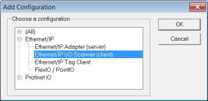
- Click the Insert Configuration icon
 to add the Fieldbus configuration.
 - Then select the EtherNet/IP I/O Scanner in the configuration selector.

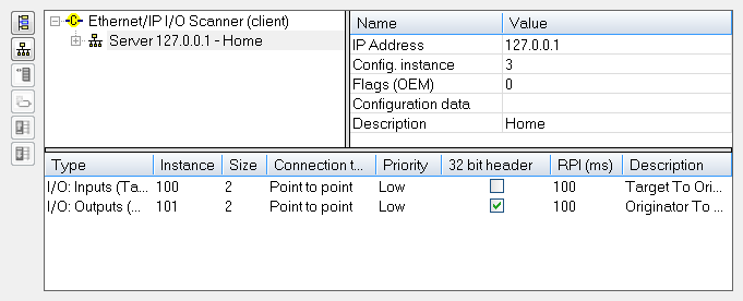
The configuration is represented as a tree:
- EtherNet/IP I/O Scanner
- Server (an EtherNet/IP adapter device) (*)
- I/O Assembly (Originator to Target)
- Exchanged Variable (*)
- Exchanged Variable (*)
- I/O Assembly (Target to Originator)
- Exchanged Variable (*)
- I/O Assembly (Originator to Target)
- Server (an EtherNet/IP adapter device) (*)
(*) The items with this mark can appear several times in the configuration.
In addition to the IO configuration, explicit messaging can be performed using the blocks eipReadAttr and eipWriteAttr.
Server Configuration
Click the Insert Master icon  to declare a server (slave adapter).
Each server is identified by its IP address and an optional Description text.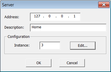
These blocks of data are exchanged with the server for each connection:
- Outputs (originator to target)
- Inputs (target to originator)
- Configuration: a static block sent to the server at connection time.
The instance number for the configuration may be specified in the properties of the server.
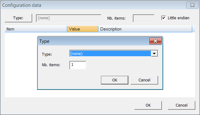
Edit the Configuration Data Block
While most devices do not expect any configuration it may happen that some data is required. For this, double click the server in the tree and click the Edit... button in the dialog box.
- The configuration is entered as a list of items.
- Use the Type button to specify the number of items and their data types.
- Structured data types defined in the KAS-IDE are supported.
- Enter values in the grid.
- If you exchange multiple byte integers (e.g., WORD), you must specify whether the device expects little or big endian formatting.
Assembly Configuration
Click the Insert Slave button ( ) to declare a CIP I/O assembly.
Each assembly is identified by:
|
Identifier |
Meaning |
|---|---|
|
Type |
Direction of the I/O assembly. Either:
|
|
Instance |
Instance of the CIP assembly. |
|
Config.instance |
The instance number of the configuration assembly. The default value is 100. |
|
Size |
Data size in bytes. |
|
Connection type |
Type of the CIP connection. Can be Point To Point or MultiCast. |
|
Priority |
CIP priority:
|
|
32-bit header |
Check this option if a 32-bit header is to be sent on notifications. |
|
RPI(ms) |
Minimum period for notification of changes in milliseconds. The range is 10 - 10000 ms. |
|
Description |
Optional description text. |
Configuring Variables
IEC 61131-3 variables may be mapped on the data of the assembly.
Each variable must have these specifications:
|
Identifier |
Meaning |
|---|---|
|
Symbol |
The name of the IEC 61131-3 variable. |
|
Offset |
Offset in bytes in the assembly data. |
|
Bit |
Bit offset in the selected byte if format is Bit. |
|
Format |
Format of the data in the assembly |
|
Mode |
Kind of data exchanged through the variable:
|
-
-
The data limit is:
500 bytes of data maximum O(originator)->T(target) and
500 bytes of data maximum T(target) -> O(originator).
This is based on the EtherNet/IP specification.


