Velocity Compensation
Velocity compensation is a value that is added to the master actual position to predict where the master will be when the new slave command position is sent to the slave.
- The compensation is used to get rid of the delay in reading the master's feedback.
- This involves prediction about where the master will be, so there is likely some small error in the prediction.
|
|
|
|
|
|
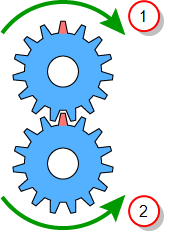
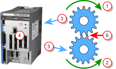
Figure 1 and Figure 2 represent a 1:-1 gearing.
- Figure 1 is ideal gearing where the master and slave are always perfectly synchronized.
- When the red tooth of the master gear is at the top, the red tooth of the slave gear is also at the top.
- Figure 2 is a real-world gearing example.
- There is a time delay in reading the master feedback position, communicating that value to the controller, and the controller communicating the new command position to the slave axis.
- This delay causes the slave to lag behind in its position.
- This is demonstrated by the slave’s read tooth being slightly out of position.
To compensate for the delay, we want to predict where the master axis will be when the new slave position applied to the slave. This is the purpose of the velocity compensation.
- Velocity compensation is controlled by two axis parameters:
- Both parameters are properties of master axes.
- When an axis is synchronized to a master via camming or gearing, the PLCopen motion engine uses these two properties of the master axis to predict where the master axis will be in the next motion cycle.
- The PLCopen motion engine then uses this predicted master position to calculate the new slave position.
Velocity Compensation Factor
The Velocity Compensation Factor (Axis Parameter 1009) is the number of motion cycles to compensate for the feedback latency.
- It should be set equal to the number of motion cycles between when the feedback device acquires the position and when the motion controller processes the position feedback.
- A value of 0 indicates no compensation is applied.
- The larger the value of Velocity Compensation Factor, the more prediction takes place and the more prediction error there will be.
- For physical axes, the value for Velocity Compensation Factor is normally 1 or 2.
- Some feedback devices or drives may require larger values.
- For virtual masters, the value is usually be 0.
- Virtual masters do not need compensation since their position is always known by the controller.
Velocity Compensation Filter
The Velocity Compensation Filter (Axis Parameter 1010) is a way to filter noisy feedback systems and/or masters that may have jitter due to servo action.
- Numerically, the Velocity Compensation Filter is the number of motion cycles over which a previously calculated compensation is applied.
- This helps smooth noisy systems.
- The default value for Velocity Compensation Filter is 1.
- No filtering takes place.
- All corrections are applied in a single cycle.
- Larger values smooth the noise, but can also cause the prediction of the master position to be further off by what is characterized as additional following error or phase delay.
- Balancing between the level of noise and the amount of phase delay is application specific and is best determined by experimentation.
- Good values typically lie in the range of 1 to 5.
See Also


