Cam Profile Editor
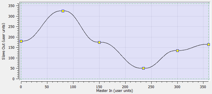
Figure 1: A cam profile
The cam profile editor is used to create and/or modify a profile definition that describes the position evolution of the cam.
- This evolution is displayed in a 2D graphical format.
- You can add, delete, or modify cam elements which consist of points and lines.
- Based on those elements and some constraints, the KAS-IDE calculates a complete cam shape.
- See Cam Profile Segment Overview for more information on the segment types.
- Master/Input (X-Axis) and Slave/Output (Y-axis) coordinates can be specified to define the position.
- It is also possible to visualize the velocity, acceleration, and jerk diagrams.
Windows Overview
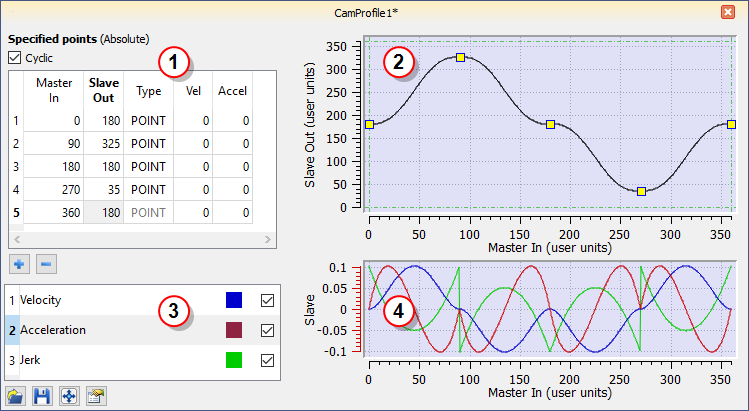
Figure 2: Cam Profile Editor Main Window
The cam profile editor contains these distinct areas separated by splitters:
- The cam table (see call out
 ) displays each element and allows editing of the cam.
 - The Graphical Area for the cam profile

The upper graph displays a graphical representation of the cam elements - The Curve Selection and Color Table
 allows you to select which plots (velocity, acceleration and jerk) are displayed
 - The Graphical Area for Curves

The lower graph displays a graphical representation of the velocity, acceleration and jerk plots
-
-
Undo (Ctrl+Z) and Redo (Ctrl+Y) operations are available for any changes you make to the cam profile.
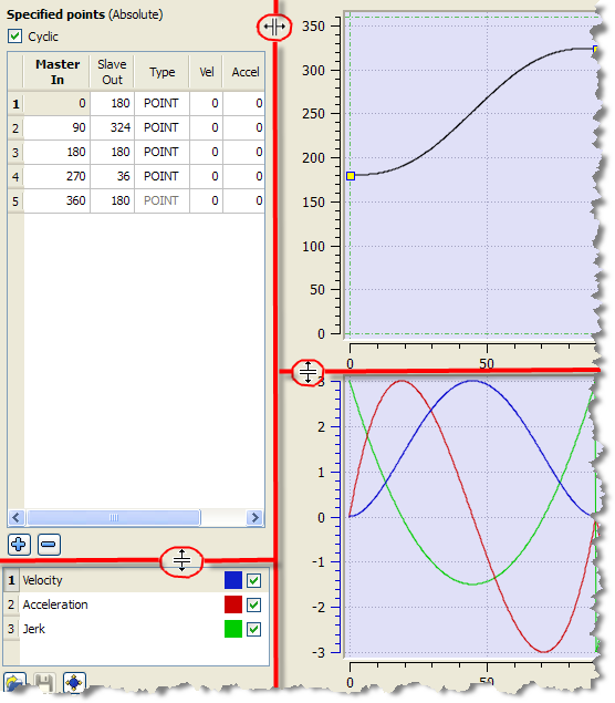
Splitters allow you to resize each part.
-
-
The tables and the graphs are separated by a vertical splitter so that you can completely hide the tables to increase the graphical area.
See Adding Cam Profiles and Profiles for more information on cam profiles.


