 Digital Inputs and Outputs
Overview
The drive has programmable digital inputs and outputs that you can use to initiate motion, control auxiliary devices, or trigger other actions. The inputs and outputs should be wired according to the instructions in the drive Installation Manual.
Using Digital I/O
Once wired correctly, digital inputs and outputs can be used for a variety of functions such as to trigger auxiliary devices, initiate homing moves or other motion tasks, or set travel limits. This section describes the specific functionality of the programmable I/O.
I/O Tip: When using I/O devices, carefully consider the type of device you use for switches. An unsuitable switch can cause switch bounce, which in turn can cause erroneous triggers to occur. For example a low cost xx switch, as it is toggled, will bounce a few times before it turns on or off. A device monitoring these inputs frequently may interpret the bounce as multiple triggers of that I/O. The drive has the ability to reduce this type of error using some debounce techniques to ignore sudden state changes caused by bounces.
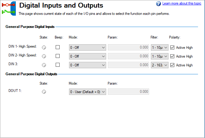
Digital Inputs
Digital inputs can be set in different modes based on the desired function. These functions
This mode is the non-use state and is the default setting for the drive. This mode is valid for all opmodes and command source combinations.
When an input configured with this mode becomes active, the drive tries to clear all active faults. This mode is edge triggered so the action occurs only once. If the condition that triggered the fault is still present, the fault condition remains. See Fault and Warning Messages for details regarding the behavior of individual faults.
This mode is valid for all opmodes and command source combinations.
This mode is used to execute four different sets of command buffers. Each set contains two buffers: low and high, for a total of eight buffers. DINx.PARAM for this mode can be 1 to 4, and determines which set of buffers to use.
To set the high and low values of the eight buffers from the terminal screen, use the commands DIN.HCMDx and DIN.LCMDx (1<=x<=4). Use ";" to separate the two buffer commands. Each buffer contains up to 128 characters.
Example
-->DIN1.MODE 9(sets command buffer mode to digital input 1)
-->DIN1.PARAM 1(sets the first set of buffers to digital input 1)
-->DIN.LCMD1 DRV.OPMOE 0;(sets low command buffer)
Under this configuration, a rising edge in digital input 1 will set DRV.OPMODE to 1 and a falling edge will set DRV.OPMODE to 0.
You can also set the command buffers from the Digital I/O view in WorkBench; see 1 Command Buffer Editor for more details on this option.
This mode is valid for all opmodes and command source combinations.
This mode is used to receive a physical home reference switch located on the machine to use for the different Home Types.
This mode is valid for opmode 2 (position) and command source 0 (service) only.
This mode is used to stop the motor using the deceleration variable ramp. If zero velocity is reached, the power stage is then disabled. Also see CS Parameters and Controlled Stop.
This mode is valid for all opmodes and command sources.
This mode is used to stop the motor. It is equivalent to issuing a DRV.STOP command.
This mode is valid for all opmodes and command sources 0 (service) and 2 (electronic gearing).
This mode is valid for opmode 2 (position) and command source 2 (electronic gearing).
Mode 18: Positive Limit Switch
This mode causes the input to operate as the positive limit switch. If the positive limit switch input is triggered (goes low), the positive direction motion is stopped.
This mode is valid for all opmodes and command source combinations.
-
-
When setting up the hardware limit switches, you must be certain that the switch remains in the triggered state until you move off of the switch. A very low deceleration rate combined with a high approach velocity may overshoot the switch. This action will cause the position limit warning to be canceled. The warning is not latched, therefore if the switch is overshot, additional movement in the same direction (if commanded) will be possible. This movement can cause machine damage.
Mode 19: Negative Limit Switch
This mode causes the input to operate as the negative limit switch. If the negative limit switch input is triggered (goes low), the negative direction motion is stopped.
This mode is valid for all opmodes and command source combinations.
-
-
When setting up the hardware limit switches, you must be certain that the switch remains in the triggered state until you move off of the switch. A very low deceleration rate combined with a high approach velocity may overshoot the switch. This action cancels the position limit warning. The warning is not latched, therefore if the switch is overshot, additional movement in the same direction (if commanded) will be possible. This movement can cause machine damage.
This mode is used to apply or release the brake when the drive is not active.
Input = 0: the drive controls the brake (regular drive behavior)
Input = 1: the user controls the brake (apply or release using commands)
This mode is valid for all opmodes and command source combinations.
-
-
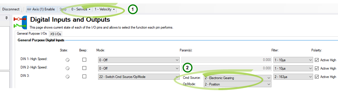
When the digital input is switched high, DRV.CMDSOURCE and DRV.OPMODE will take the values defined by DINx.PARAM. Do not perform a “drive save” in this state, or the low state and high state settings will become the same.
Suspend Motion is a feature which stops current motion, suspends further motion, but keeps the drive enabled. The axis decelerates at the rate defined by CS.DEC (pg 1).
Motion is being disallowed by Suspend Motion when DRV.MOTIONDISSOURCES = 1.
Digital Outputs
Digital outputs can be set in different modes based on the desired function. These functions
-
-
If an output is overloaded (> 100 mA), then the output will turn off (with no indication in WorkBench) and remain off until one of the following occurs:
- The power supply driving the output is removed.
- The output is turned off from the firmware.
- The 24V supply to the AKD is power cycled.
Mode 0 – User (Default = 0):The output state is decided by the user or fieldbus. This mode is valid for all opmodes and command source combinations.
Mode 1 – Mains Ready: The output mode produces a high signal if the drive DC bus voltage is higher than the under voltage error level and lower than the over voltage error level. This mode is valid for all opmodes and command source combinations.
Mode 10 – Motor Brake: The output mode produces a high signal if a brake is released (this is when the power is applied to the brake and the motor is free to spin). The output mode produces a low if a brake is applied (this is when power is removed from the brake and the brake is set).
This mode is valid for all opmodes and command source combinations.
Mode 15 – Programmable Limit Switch Output: The output mode produces a high signal if at least one of the PLS.STATE bits is high (the PLS is active) and if the corresponding bit in the DOUTx.PARAM parameter also has been set to high. The DOUTx.PARAM command connects the PLS.STATE bits to the digital output itself and thus acts as an enable mask.
In mode 15 DOUTx.PARAM is set from the Digital Outputs section of the Programmable Limit Switches screen. See Programmable Limit Switch.
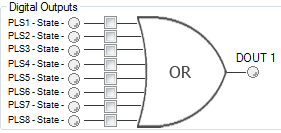
This mode is valid for all opmodes and command source combinations.
Example
|<- Bit 7 to 0 ->|
DOUT1.PARAM = 23 = 0b 0 0 0 1 0 1 1 1 (Binary code)
The digital output 1 is active when bit 0 or bit 1 or bit 2 or bit 4 of PLS.STATE is high. All other bits within PLS.STATE are not considered by the digital output mode due to the DOUT1.PARAM setting. Do not use decimal places for the DOUTx.PARAM parameter for this particular digital output mode.
Summary of Opmode and Command Source Dependencies
| DINx.MODE | Mode Description | Opmode | Command Source |
|---|---|---|---|
|
0 |
Off |
All |
All |
|
1 |
Fault Reset |
All |
All |
|
10 |
Control Fault Relay |
All |
All |
|
15 |
Quick Stop |
All |
0 - Service |
| DOUTx.MODE | Mode Description | Opmode | Command Source |
|---|---|---|---|
|
0 |
User (Default = 0) |
All |
All |
|
10 |
Motor Brake |
All |
All |
|
15 |
Programmable Limit Switch State |
All |
All |


