


SS1-t (Safe Stop 1)
SS1-t (time controlled) description for drive option Functional Safety 2 or 3.
Description
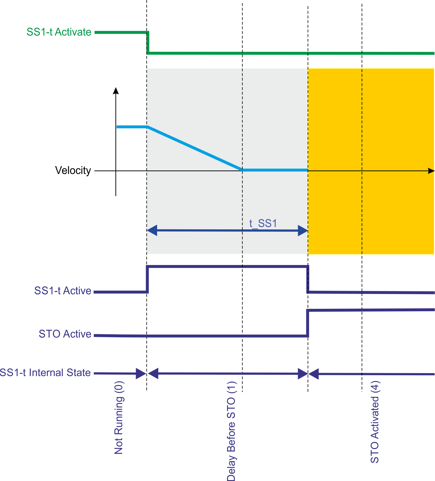
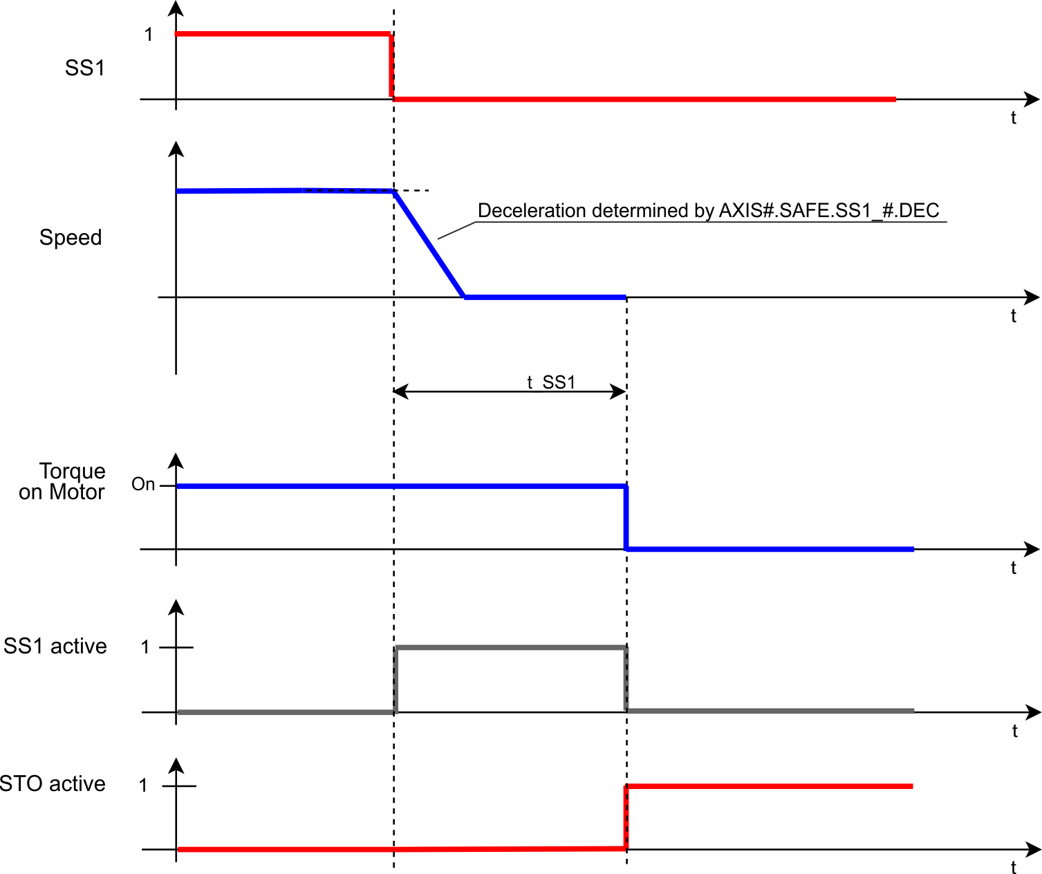
With the time based function "Safe Stop 1" (SS1-t) the drive is stopped by a controlled stop with the configured deceleration ramp. When the time t_SS1 (➜ # 1, AXIS#.SAFEPARAM.SS1_#.TIMETOSTO) is elapsed, STO is activated.
SS1 function corresponds to a controlled stop according to IEC 60204-1, stop category 1. The controlled stop is executed in the unsafe part of the drive. The deceleration ramp (➜ # 1, AXIS#.SAFE.SS1_#.DEC) is part of the standard drive parameter. The STO function is a safe function.
Function Input / Output Variables
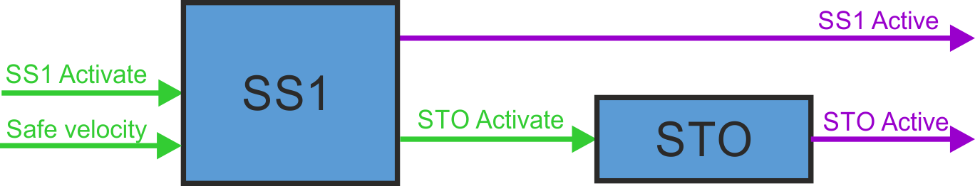
Inputs
- SS1 Activate can be activated by
- FSoE,
- I/O failure (instance 1 only),
- safe digital inputs (must be mapped) or
- other safety functions as fault reaction.
Outputs
- SS1 Active: logical status of the SS1 function
- STO Active: logical status of the STO function
- STO Activate is activated by SS1
Number of Instances
Three instances per axis.
Activation

|
To use SS1-t, Velocity & Deceleration Monitoring must be disabled in the safety parameters on a FS3 drive. On a FS2 drive, only SS1-t is available. If SS1_2 or SS1_3 is set to “Not Used”, the corresponding FSoE activation bit is ignored even if (➜ # 1, SAFEPARAM.SAFEFIELDBUS.ACTIVATION) is 1. |
|
Activation by FSoE |
|
|
Activation by safe digital inputs |
|
Safety Properties
Refer to (➜ # 1, Safety Properties Overview).
Restart
(➜ # 1, STO (Safe Torque Off))
Timing
Notes:
- SS1 is fully completed after activation until STO is activated, even if the request (SS1_Activate) is reset in between.
- The additional time for the optional closing of the brakes is not included in this diagram. For more information refer to (➜ # 1, SBC (Safe Brake Control))
- See limitations for FSoE
Related Parameters
Safety parameters
|
Name |
Variables |
Default |
Parameter |
|---|---|---|---|
|
Function Activation |
- |
Inst. 1: 1 (Ready for activation) |
|
|
Safe Input |
- |
0 (Not used) |
|
|
FSoE |
- |
0 (Not used) |
|
|
Time To STO |
t_SS1 |
2 ms |
|
|
Velocity & Deceleration Monitoring |
- |
0 (Disabled) |
Diagnostic parameters
|
Name |
Variables |
Default |
Parameter |
|---|---|---|---|
|
Function Active Status |
- |
- |
|
|
Function Internal Status |
- |
- |
Device parameters
|
Name |
Variables |
Default |
Parameter |
|---|---|---|---|
|
Deceleration Mode |
- |
0 (Drive driven) |
|
|
Deceleration Ramp |
- |
9999.946 rpm/s |
State Diagram
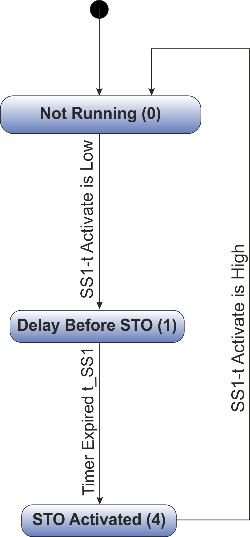
SS1-t is active when its internal state is in state "Delay Before STO (1)".
Setup in WorkBench
Select the drive and open the Safety Parameterization view (➜ # 1, Parameters Editor).
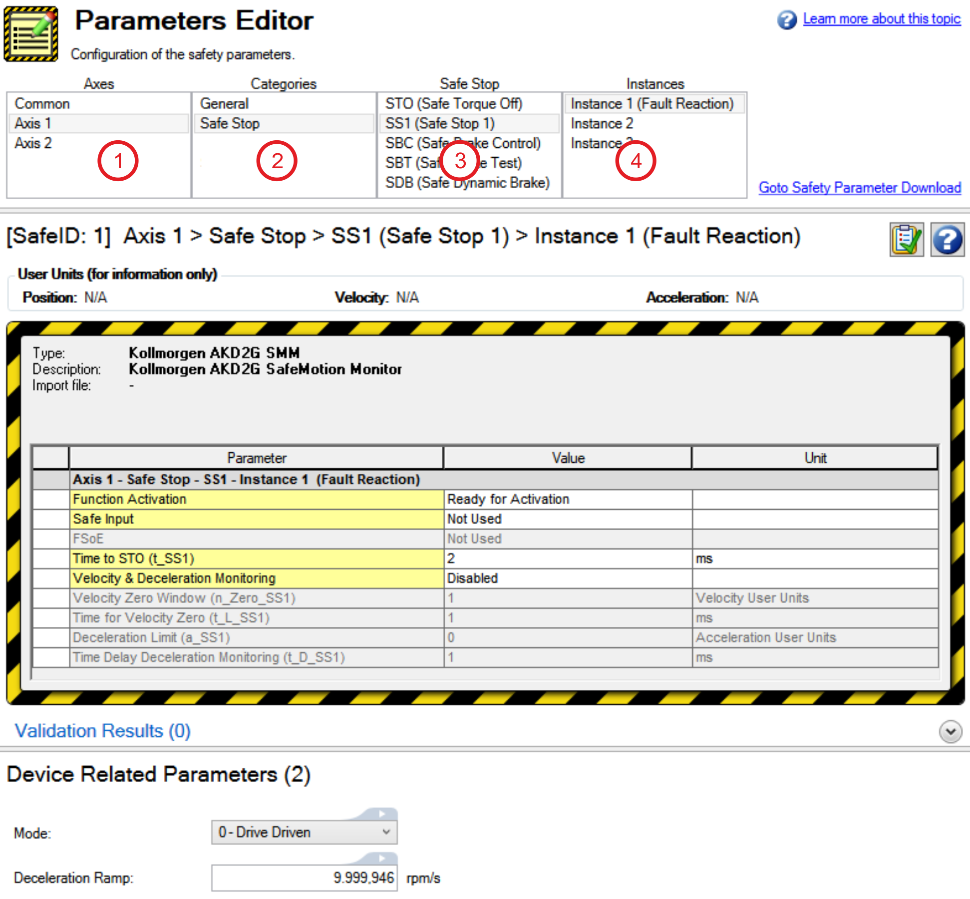
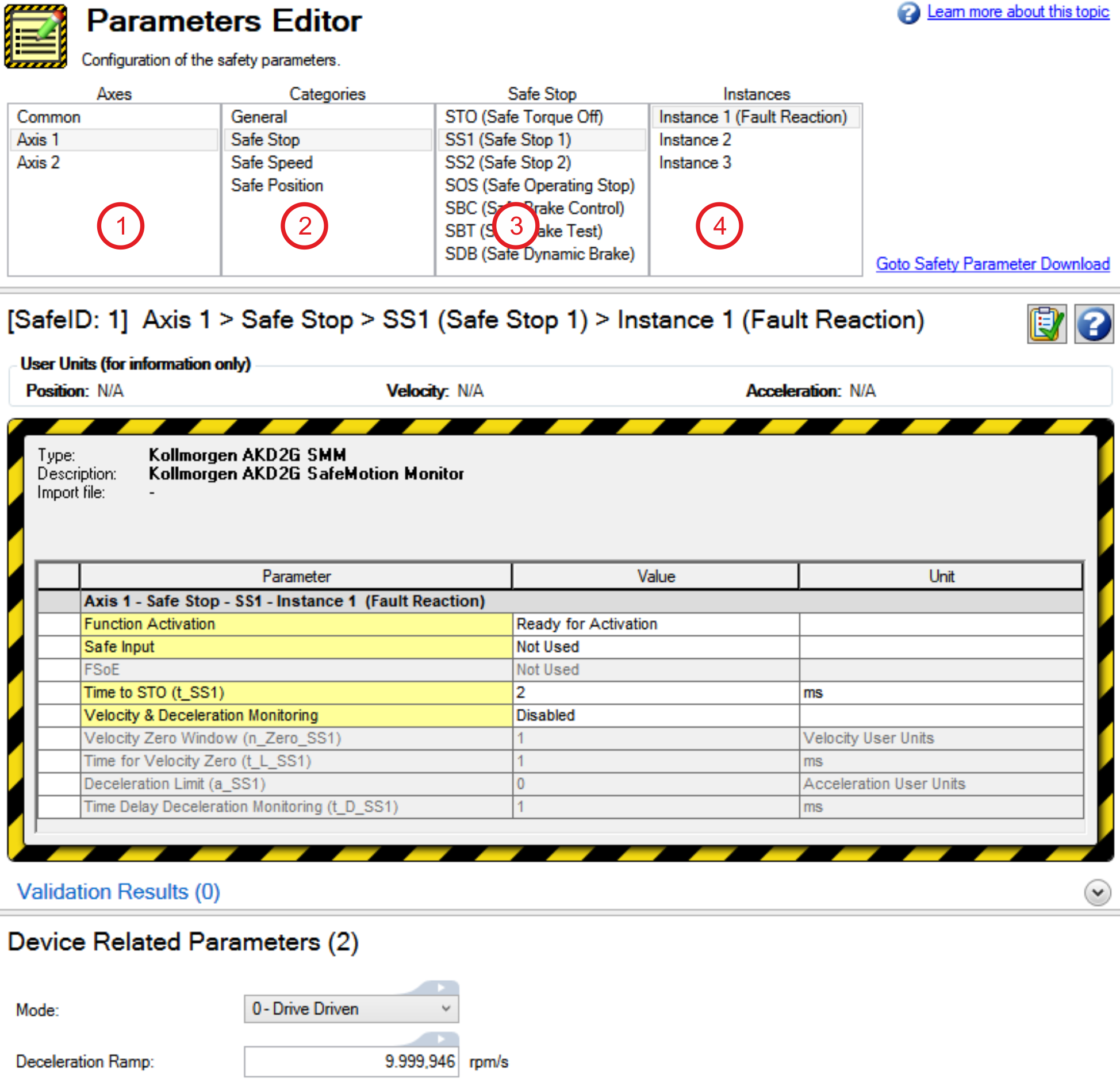
|
|
If one dual input (e.g. SIN1/SIN2) activates SS1-t for both Axis 1 and Axis 2, set the Activation parameter for both axes to the identical input (e.g. Safe Dual Input 1).
Fault Reaction / Failure Messages
If dual channel mode is selected, the AKD2G sees if the two inputs are in a different state for more than 100 ms. If the two inputs are in different state for more than 100 ms, an I/O failure activates SS1_1 and then STO is activated. An I/O failure warning is displayed.
SS1 Instance 1 can be configured as the fault reaction for other safety functions. Functions which support this feature are SS2, SSR, SDI, SLA, SAR, SLI, SLP and SLS.
Safety State / Status Signals
The signal AXIS#.SAFE.SS1_#.ACTIVE can be monitored by safe digital outputs with OSSD pulses (➜ # 1, OSSD). The status signal must be mapped to the safe digital output. Two outputs can be combined to a dual channel output. For parameter description see (➜ # 1, Functional Safety Parameter Reference).


