


SSR (Safe Speed Range)
SSR description for drive option Functional Safety 3.
Description
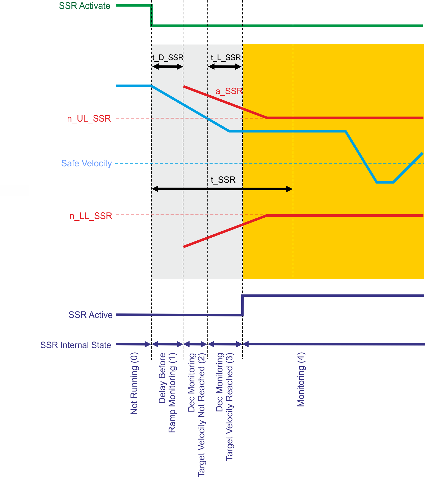
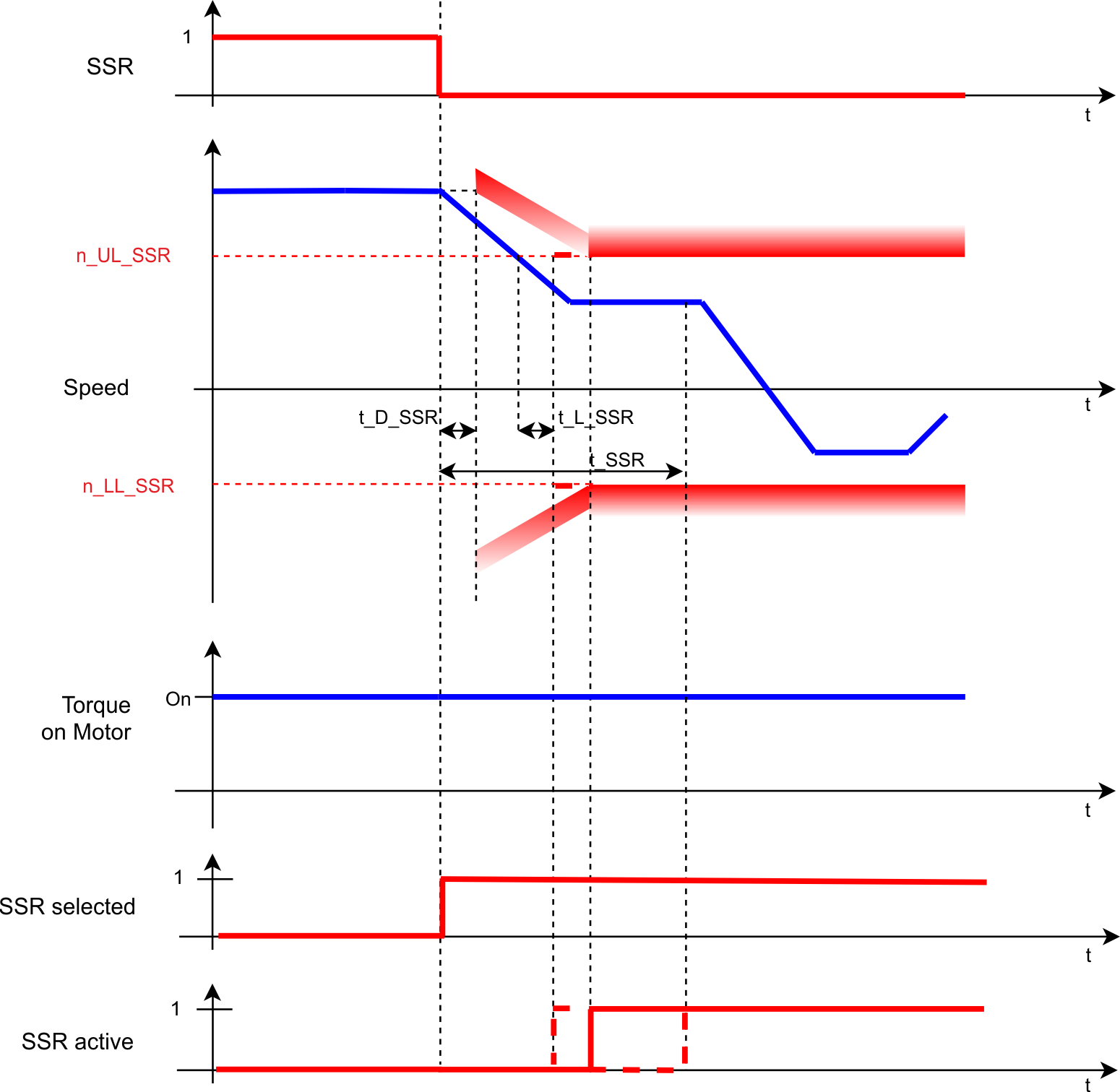
SSR, when activated, monitors the velocity and ensures that it stays in a configured velocity window. The parameter n_UL_SSR defines the upper limit and the parameter n_LL_SSR defines the lower limit of this window. If the velocity leaves the velocity window a configurable fault reaction will be activated.
Once the activation request is received, SSR will become active depending on what occurs first:
- The time to velocity monitoring is elapsed (t_SSR)
- The current velocity stays in the configured velocity window for a given amount of time (t_L_SSR)
Optionally, the deceleration ramp can be monitored after some delay (t_D_SSR) to check whether the current velocity is below the computed velocity ramp (a_SSR). If the velocity is above the computed velocity ramp, the fault reaction will be activated.
Number of Instances
Three instances per axis.
Function Input / Output Variables
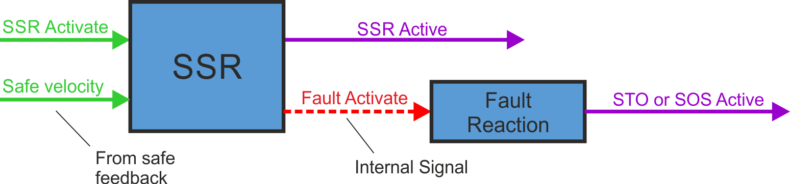
Inputs
- SSR Active can be triggered by FSoE or safe digital inputs (must be mapped)
- Safe velocity: velocity signal from safe feedback
Outputs
- SSR Active: logical status of the SSR function
- Fault Activate: activate fault reaction
Activation
|
Activation by FSoE |
|
|
Activation by safe digital inputs |
|
Timing
Related Parameters
Safety parameters
|
Name |
Variables |
Default |
Parameter |
|---|---|---|---|
|
Function Activation |
- |
0 (Never active) |
AXIS#.SAFEPARAM.SSR_#.FUNCTIONACTIVATION |
|
Safe Input |
- |
0 (Not used) |
|
|
FSoE |
- |
0 (Not used) |
|
|
Time To Velocity Monitoring |
t_SSR |
2 ms |
|
|
Velocity Upper Limit |
n_UL_SSR |
0 (Vel user units) |
|
|
Velocity Lower Limit |
n_LL_SSR |
0 (Vel user units) |
|
|
Time For Velocity in Limits |
t_L_SSR |
1 ms |
|
|
Deceleration Monitoring |
- |
0 (Disabled) |
|
|
Deceleration Limit |
a_SSR |
0 (Dec user units) |
|
|
Time Delay Deceleration Monitoring |
t_D_SSR |
1 ms |
|
|
Fault Reaction |
- |
1 (STO) |
Diagnostic parameters
| Name |
Variables |
Default |
Parameter |
|---|---|---|---|
|
Function Active Status |
- |
- |
|
|
Function Internal Status |
- |
- |
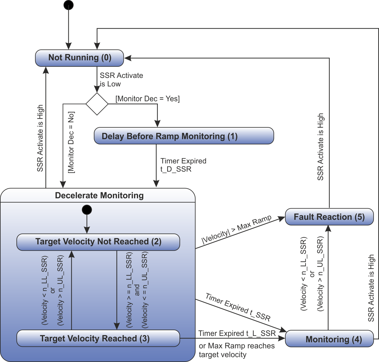
SSR is active if internal state is "Monitoring (4)" or "Fault reaction (5)".
Setup in WorkBench
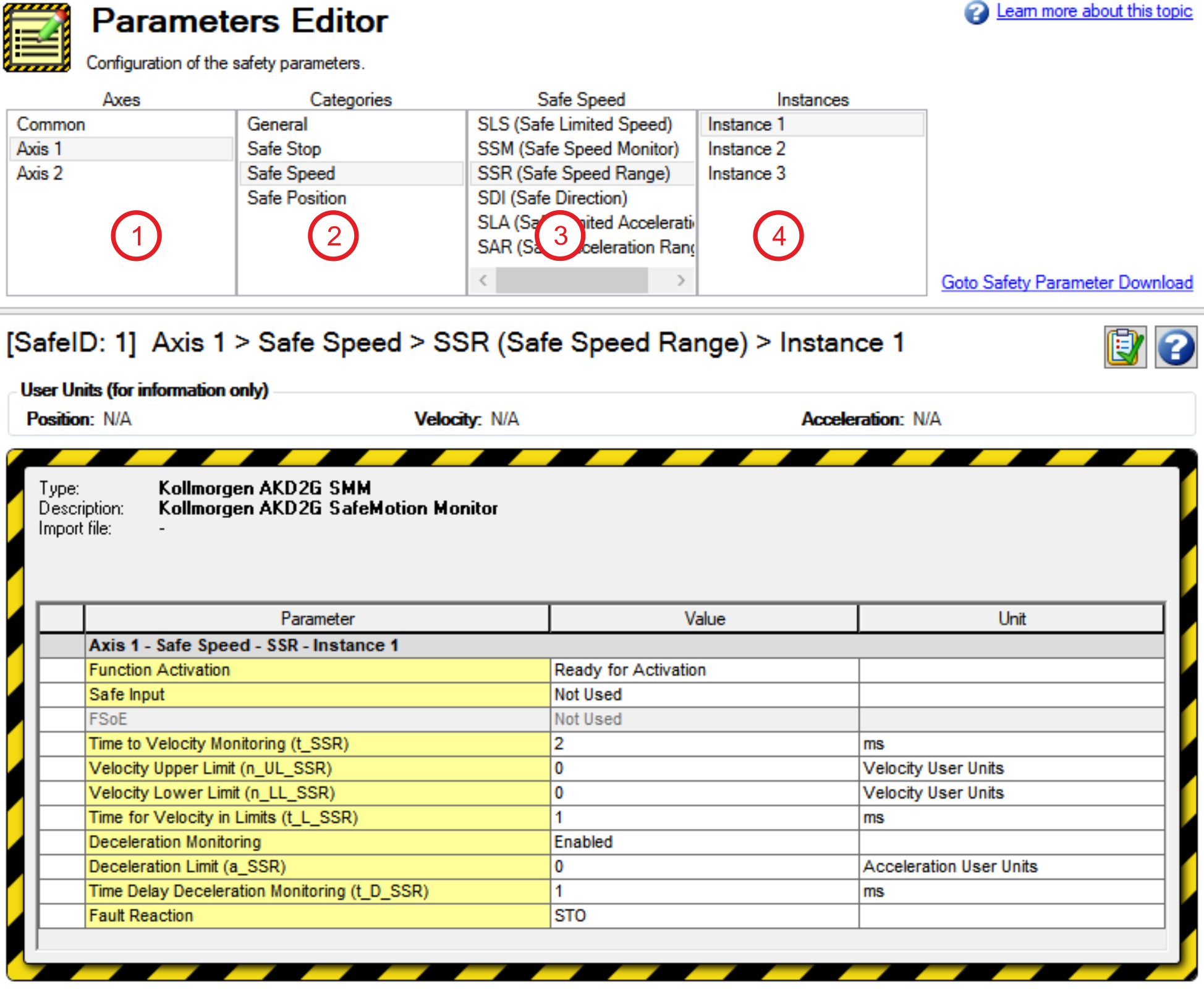
Select the drive and open the Safety Parameterization view (see "Parameters Editor").
Choose the axis (1), category (2), SSR function (3) and the instance number (4).
Fault Reaction / Failure Messages
SSR has a configurable fault reaction. STO is used by default but can be replaced by SS1 Instance 1 or SS2 Instance 1. When the fault reaction is activated, SSR remains active and the internal state
(AXIS#.SAFE.SSR_#.INTERNALSTATE) is set to failed state (5).
Safety State / Status Signals
The signal AXIS#.SAFE.SSR_#.ACTIVE can be monitored by safe digital outputs with OSSD pulses (see "OSSD"). The status signal must be mapped to the safe digital output. Two outputs can be combined to a dual channel output. For parameter description refer to Functional Safety Parameter Reference.
Safety Properties
Refer to (➜ # 1, Safety Properties Overview).


