![]()
 Function Block - Homing to a home switch.
Inputs
|
Input |
Data Type |
Range |
Unit |
Default |
Description |
|---|---|---|---|---|---|
|
Execute |
BOOL |
FALSE, TRUE |
N/A |
No default |
Request the homing step procedure at the rising edge. Outputs are reset when execute input is FALSE. |
|
AxisID |
AXIS_REF |
1 to 256 |
N/A |
No default |
Name of a declared instance of the AXIS_REF library function. See AXIS_REF Structure. |
|
Direction |
DINT |
0, 3 |
N/A |
No default |
Defines the axis homing direction.
|
|
SwitchMode |
DINT |
0, 3 |
N/A |
No default |
Switch state to complete homing.
|
|
Velocity |
LREAL |
No range |
User unit/sec |
No default |
Commanded velocity for the homing move. |
|
Acceleration |
LREAL |
No range |
User unit/sec2 |
No default |
Commanded acceleration for the homing move. |
|
Deceleration |
LREAL |
No range |
User unit/sec2 |
No default |
Commanded deceleration for the homing move. |
|
Jerk |
LREAL |
No range |
User unit/sec3 |
No default |
Commanded jerk for the homing move. If 0 (zero), trapezoidal acc/dec is used. |
|
TorqueLimit |
LREAL |
No range |
User units |
No default |
Maximum torque applied for the homing move.
|
|
TimeLimit |
TIME |
No range |
Sec |
No default |
Maximum time for homing move to complete.
|
|
DistanceLimit |
LREAL |
No range |
User units |
No default |
Maximum distance for homing move to complete.
|
|
AbsoluteSwitch |
BOOL |
FALSE, TRUE |
N/A |
No default |
The absolute switch input I/O point. |
|
PosLimitSwitch |
BOOL |
FALSE, TRUE |
N/A |
No default |
The positive direction limit switch input I/O point. |
|
NegLimitSwitch |
BOOL |
FALSE, TRUE |
N/A |
No default |
The negative direction limit switch input I/O point. |
|
SwitchMode |
SINT |
0, 5 |
N/A |
No default |
Switch state to complete homing.
|
Outputs
|
Output |
Data Type |
Range |
Unit |
Description |
||||||||||||||
|---|---|---|---|---|---|---|---|---|---|---|---|---|---|---|---|---|---|---|
|
Done |
BOOL |
FALSE, TRUE |
N/A |
Indicates the move completed successfully. |
||||||||||||||
|
Busy |
BOOL |
FALSE, TRUE |
N/A |
High from the moment the Execute input goes high until the time the move is ended. |
||||||||||||||
|
Active |
BOOL |
FALSE, TRUE |
N/A |
Indicates this move is the Active move. |
||||||||||||||
|
CommandAborted |
BOOL |
FALSE, TRUE |
N/A |
Indicates the move was aborted. |
||||||||||||||
|
Error |
BOOL |
FALSE, TRUE |
N/A |
Indicates either:
|
||||||||||||||
|
ErrorID |
INT |
Enumerated |
N/A |
Indicates the error if the Error output is set to TRUE. Error identifier:
|
Remarks
- Performs a homing function by searching for an absolute positioned external physical switch.
- An Absolute Switch has two Off (or On) areas.
This image shows the function or function block I/O.
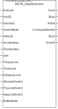
Figure 1: MCFB_StepAbsSwitch
Usage
This physical layout has the risk that homing is started in the wrong direction (escaping the switch).
To support such case, it implements a special behavior when Limit Switches are found (or the AbsSwitch itself is On at Execute).
- This function block does not modify the actual position.
- The homing is commanded in the most likely direction where the sensor can be found.
- The Velocity is defined by the input.
- The Torque is limited.
- Time and Distance Limits can cause an error if exceeded.
- If any LimitSwitch is found during Homing (any of them), a special process is started in the opposite direction.
- The AbsSwitch is searched to switch Off (or On, depending on SwitchMode setting).
- The Edge (passed by) and homing process is restarted in the original direction and with the same conditions.
- This ensures the end conditions are always the same.
- If the SwitchMode is either MC_SwitchNegative or MC_SwitchPositive, then the special process is also started in opposite direction depending from the switch state at Execute.
- The direction changes only when the specified Velocity is reached.
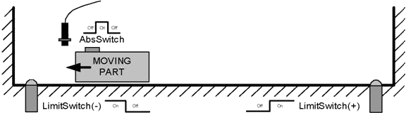
Figure 2: MCFB_StepAbsSwitch Usage 1
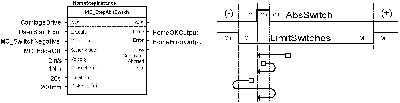
Figure 3: MCFB_StepAbsSwitch Usage 2
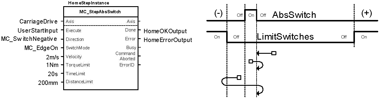
Figure 4: MCFB_StepAbsSwitch Usage 3
An overlapping switch configuration is also possible.
This has same the behavior as working on the limit switches:
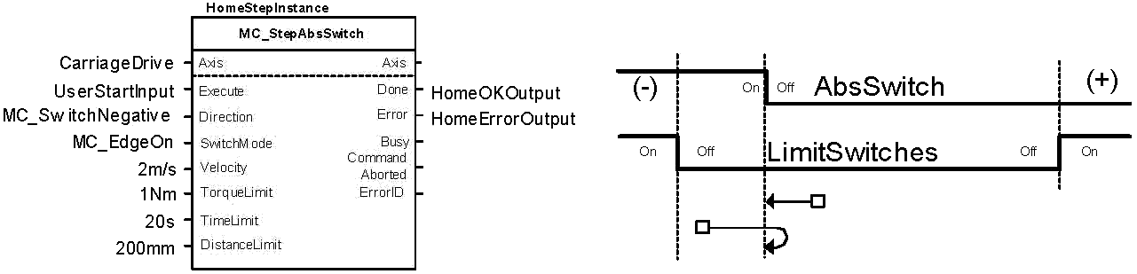
Figure 5: MCFB_StepAbsSwitch Usage 4
If the input Direction is set to a fixed direction (MC_Positive or MC_Negative), then the initial switch state is ignored.
Used for example in rotary axis where only one sense of rotation is allowed:
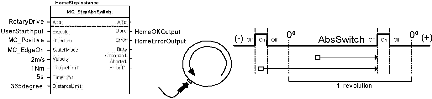
Figure 6: MCFB_StepAbsSwitch Usage 5
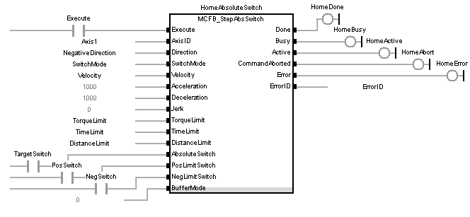
FBD Language Example
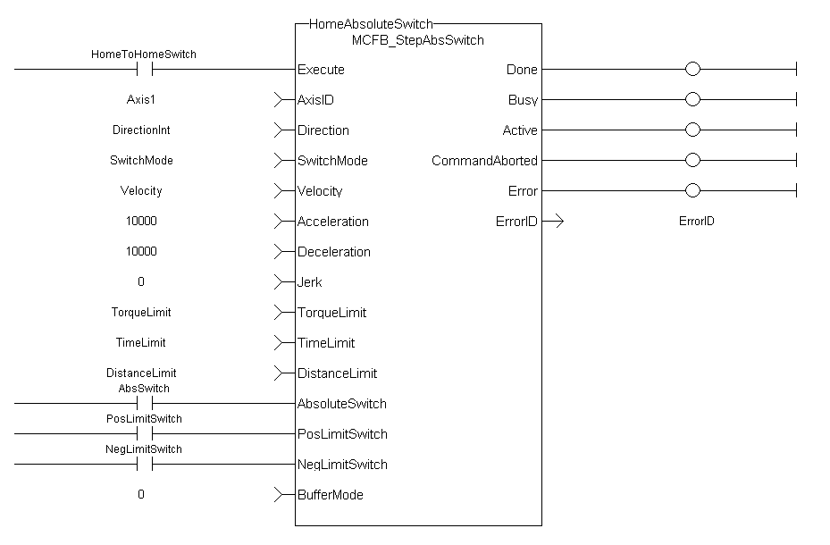
FFLD Language Example
IL Language Example
Not available.
ST Language Example
NegativeDirection :=1;
RisingEdge :=2;
Velocity :=10000.0;
TorqueLimit :=50.0;
TimeLimit :=T#10s;
DistanceLimit :=10000.0;

Inst_MCFB_StepAbsSwitch( True, Axis1, NegativeDirection, RisingEdge, Velocity, 1000, 1000, 0, TorqueLimit, TimeLimit, DistanceLimit, AbsoluteSwitch, PosLimitSwitch, NegLimitSwitch, 0 );

HomeComplete :=Inst_MCFB_StepAbsSwitch.Done;
HomeBusy :=Inst_MCFB_StepAbsSwitch.Busy;
HomeActive :=Inst_MCFB_StepAbsSwitch.Active;
HomeAborted :=Inst_MCFB_StepAbsSwitch.CommandAborted;
HomeError :=Inst_MCFB_StepAbsSwitch.Error;
HomeErrorID :=Inst_MCFB_StepAbsSwitch.ErrorID;
(* AbsoluteSwitch, PosLimitSwitch, NegLimitSwitch are declared I/O points *)
See Also


