![]()
 Function Block - Homing to a limit switch.
Inputs
|
Input |
Data Type |
Range |
Unit |
Default |
Description |
|---|---|---|---|---|---|
|
Execute |
BOOL |
FALSE, TRUE |
N/A |
No default |
Request the homing step procedure at the rising edge. Outputs are reset when execute input is FALSE. |
|
AxisID |
AXIS_REF |
1 to 256 |
N/A |
No default |
Name of a declared instance of the AXIS_REF library function. See AXIS_REF Structure. |
|
Direction |
BOOL |
FALSE, TRUE |
N/A |
No default |
Defines the axis homing direction.
|
|
LimitSwitchMode |
DINT |
0, 3 |
N/A |
No default |
Limit switch state to complete homing.
|
|
Velocity |
LREAL |
No range |
User unit/sec |
No default |
Commanded velocity for the homing move. |
|
Acceleration |
LREAL |
No range |
User unit/sec2 |
No default |
Commanded acceleration for the homing move. |
|
Deceleration |
LREAL |
No range |
User unit/sec2 |
No default |
Commanded deceleration for the homing move. |
|
Jerk |
LREAL |
No range |
User unit/sec3 |
No default |
Commanded jerk for the homing move. If 0 (zero), trapezoidal acc/dec is used. |
|
TorqueLimit |
LREAL |
No range |
User units |
No default |
Maximum torque applied for the homing move.
|
|
TimeLimit |
TIME |
No range |
Sec |
No default |
Maximum time for homing move to complete.
|
|
DistanceLimit |
LREAL |
No range |
User units |
No default |
Maximum distance for homing move to complete.
|
|
LimitSwitch |
BOOL |
FALSE, TRUE |
N/A |
No default |
The limit switch input I/O point. |
|
BufferMode |
SINT |
0, 5 |
N/A |
No default |
Define the homing move start action.
|
Outputs
|
Output |
Data Type |
Range |
Unit |
Description |
||||||||||||||
|---|---|---|---|---|---|---|---|---|---|---|---|---|---|---|---|---|---|---|
|
Done |
BOOL |
FALSE, TRUE |
N/A |
Indicates the move completed successfully. |
||||||||||||||
|
Busy |
BOOL |
FALSE, TRUE |
N/A |
High from the moment the Execute input goes high until the time the move is ended. |
||||||||||||||
|
Active |
BOOL |
FALSE, TRUE |
N/A |
Indicates this move is the Active move. |
||||||||||||||
|
CommandAborted |
BOOL |
FALSE, TRUE |
N/A |
Indicates the move was aborted. |
||||||||||||||
|
Error |
BOOL |
FALSE, TRUE |
N/A |
Indicates either:
|
||||||||||||||
|
ErrorID |
INT |
Enumerated |
N/A |
Indicates the error if the Error output is set to TRUE. Error identifier:
|
Remarks
- Performs a single-axis home to a limit switch.
- The limit switches are used for homing procedure.
- They are always active once moving part working area has been surpassed.
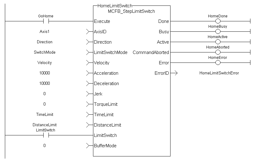
This image shows the function or function block I/O.
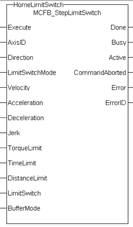
Figure 1: MCFB_StepLimitSwitch
Usage
- This function block does not modify the actual position.
- Home is commanded by the user in the designated homing direction at the selected or programmed Velocity.
- This procedure performs a homing function searching for sensor using only LimitSwitches.
- A LimitSwitch has one Off (or On) area.
- If LimitSwitch is found On with a rising Execute, the process is started in the opposite direction as specified.
- LimitSwitch is searched for Off Edge (released) and process is restarted again in original direction.
- Or On, depending on LimitSwitchMode setting.
- This ensures the end conditions are always the same.
- The Torque is limited.
- Time and Distance Limits can cause an error if exceeded.
- The direction changes only when the specified Velocity is reached.
- This ensures acceleration and deceleration spaces are fixed.
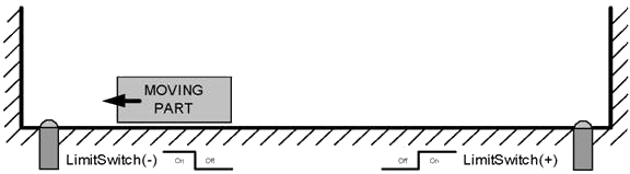
Figure 2: MCFB_StepLimitSwitch Usage 1
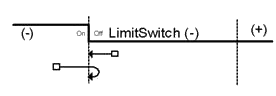
Figure 3: MCFB_StepLimitSwitch Usage 2
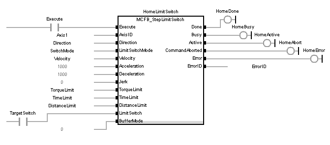
FBD Language Example
FFLD Language Example
IL Language Example
Not available.
ST Language Example
PositiveDirection :=0;
RisingEdge :=2;
Velocity :=10000.0;
TorqueLimit :=50.0;
TimeLimit :=T#10s;
DistanceLimit :=10000.0;

Inst_MCFB_StepLimitSwitch( True, Axis1, PositiveDirection, RisingEdge, Velocity, 1000, 1000, 0, TorqueLimit, TimeLimit, DistanceLimit, LimitSwitch, 0 );

HomeComplete :=Inst_MCFB_StepLimitSwitch.Done;
HomeBusy :=Inst_MCFB_StepLimitSwitch.Busy;
HomeActive :=Inst_MCFB_StepLimitSwitch.Active;
HomeAborted :=Inst_MCFB_StepLimitSwitch.CommandAborted;
HomeError :=Inst_MCFB_StepLimitSwitch.Error;
HomeErrorID :=Inst_MCFB_StepLimitSwitch.ErrorID;

(* LimitSwitch is a declared I/O point *)
See Also


