MLGearInit
![]()
 Function - Initializes a Gear Pipe Block with user-defined settings and for use in a PLC program.
Inputs
|
Input |
Data Type |
Range |
Unit |
Default |
Description |
|---|---|---|---|---|---|
|
BlockID |
DINT |
-2147483648 to 2147483647 |
N/A |
No default |
ID number of a created Pipe Block. |
|
Ratio |
LREAL |
No range |
N/A |
No default |
Ratio of new Gear Pipe Block.
|
|
Offset |
LREAL |
No range |
N/A |
No default |
Offset of new Gear Pipe Block.
|
|
UseUserRatioSlope |
BOOL |
FALSE, TRUE |
N/A |
No default |
FALSE to use the maximum Slope.
|
|
RatioSlope |
LREAL |
No range |
1/sec |
No default |
User-defined limit at which step changes in Ratio are implemented.
|
|
UseUserOffsetSlope |
BOOL |
FALSE, TRUE |
N/A |
No default |
FALSE to use the maximum Slope.
|
|
OffsetSlope |
LREAL |
No range |
User unit/sec |
No default |
User-defined limit at which step changes in Offset are implemented.
|
|
Modulo |
BOOL |
FALSE, TRUE |
N/A |
No default |
TRUE when the mode is modulo. Modulo mode adapts the output values according to the ModuloPosition (modulo). |
Outputs
|
Output |
Data Type |
Range |
Unit |
Description |
|---|---|---|---|---|
|
Default (.Q) |
BOOL |
FALSE, TRUE |
N/A |
Returns TRUE if the Gear Pipe Block is initialized.
|
Remarks
- This function block is automatically called if a Gear Block is added to the Pipe Network, with user-defined settings entered in the Pipe Blocks Properties screen.
- The Pipe Block is assigned a Name, Ratio, Offset, and Slopes for changes in Ratio and Offset values.
- Choose between Modulo or Not modulo mode.
- Slopes set the limit at which step changes in Ratio and Offset are implemented.
-
-
Set the
RatioSlope < (Ratio * EtherCAT Update Rate).
The Gear block makes a jump (without a ramp) from one gear to the next when the RatioSlope is greater than the Ratio change factor multiplied by the update rate scale factor.
Modulo Value
If the Gear block's input is a modulo value and the position delta is greater than ½, the modulo value within one sample period in the opposite direction, the Gear block cannot detect the change in the direction of motion.
Example
- The sample period is: 1 msec.
- The Master is configured for a 360 degree modulo.
- The Master position is changed by >180 degrees within 1 msec.
- In this case, the Gear block cannot determine whether the direction is in the same or opposite direction.
Avoid Modulo Calculation Problems
- Either deactivate and reactivate the PipeNetwork when forcing the Master position with MLMstForcePos.
- Use a MLMstAbs or MLMstRel move to force the Master’s position value.
Example
To force the Master position to 0 (zero), use this code:
PipeNetwork(MLPN_DEACTIVATE);
MLMstForcePos(PipeNetwork.MASTER, 0);
PipeNetwork(MLPN_ACTIVATE);
-
-
Gear objects are normally created in the Pipe Network using the graphical engine.
You do not have to add MLGearInit function blocks to their programs.
Parameters are entered directly in pop-up windows and the code is automatically added to the current project.
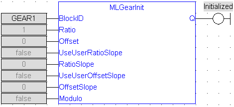
FBD Language Example
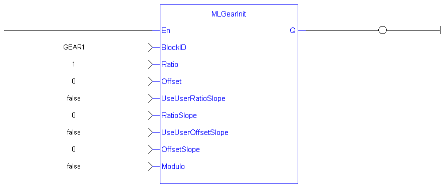
FFLD Language Example
IL Language Example
Not available.
ST Language Example
//Initialize a Gear Pipe Block named GEAR1 with:
//  Ratio = 1,Offset = 0, User Ratio Slope OFF, User Ratio
//  Slope = 0, Offset Slope = 0, and no Modulo
GEAR1 := MLBlkCreate( 'GEAR1', 'GEAR' );
MLGearInit( GEAR1, 1.0, 0.0, false, 0.0, false, 0.0, false);
See Also


