Free Form Ladder Diagram (FFLD)
- Each rung represents a Boolean data flow from a power rail on the left.
- The power rail represents the TRUE state.
- The data flow must be understood from the left to the right.
- Each symbol connected to the rung either changes the rung state or performs an operation.
- These are possible graphic items to be entered in FFLD diagrams:
- Power Rails
- FFLD Contacts and Coils
- Operations, Functions and Function blocks, represented by rectangular blocks.
Use of EN Input and ENO Output for Blocks
The rung state in a FFLD diagram is always Boolean.
- Blocks are connected to the rung with their first input and output.
- This implies that special EN and ENO input and output are added to the block if its first input or output is not Boolean.
- The EN input is a condition.
- It means that the operation represented by the block is not performed if the rung state (EN) is FALSE.
- The ENO output always represents the sane status as the EN input.
- The rung state is not modified by a block having an ENO output.
Examples
- This is an example of XOR / XORN with Boolean inputs and outputs and requiring no EN or ENO pin.
- First input is the rung.
- The rung is the output.
- This is an example of the GT > (greater than) with non-Boolean inputs and a Boolean output.
- This block has an EN input in FFLD.
- The comparison is executed only if EN is TRUE.
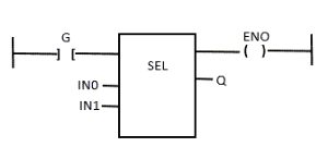
- This is an example of the sel with a first Boolean input but an integer output.
- This block has an ENO output in FFLD.
- The input rung is the selector.
- ENO has the same value as SELECT.
- This is an example of Addition + having only numerical arguments.
- This block has both EN and ENO pins in FFLD.
- The addition is executed only if EN is TRUE.
- ENO has the same value as EN.

See Also


