|
Name |
Description |
|
Verifies if the reference of a comparator Pipe Block has been crossed. |
|
|
Initializes a comparator Pipe Block with user-defined settings for use in a PLC Program. |
|
|
Clears the Transition Flag of a comparator Pipe Block. |
|
|
Sets the reference position of a comparator block. |
Purpose
A Comparator monitors the flow of pipe data and causes a specified action when the flow of values at its input crosses a specified reference value.
- A Comparator is used for synchronizing the operation of an actuator to the position of a product or axis in a machine cycle.
- The Comparator block does not modify flow values and has no effect on the axis and its periodicity.
Parameters
The necessity to use the through zero reference mode is illustrated in this example.
Assume:
- The system is a periodic system with a Modulo Position of 500.
- The system is running in the positive direction (pipe flow values increase).
- Imagine that the position of the system is
now 400 and you want to wait for the system to reach 326 again.
- If you ask for the Comparator to detect the 326 reference in normal mode, it immediately sets the ready flag at true (400 > 326) but this is not what you want.
- If you ask for the Comparator to detect the 326 value in through zero reference mode, it waits for the system to cross one zero reference (cross the position value = 0) and then triggers the application when the correct condition is fulfilled.
There is a big difference in response time when using a Boolean equation to compare a value with a reference, versus using a Comparator pipe block do to the same processing.
- With the Boolean equation, KAS periodically performs the comparison, ignoring any dynamics taking place between successive comparisons, which could result in delays in triggering sequences, and possible loss of information when the pipe-flow value crosses the reference momentarily between comparisons.
- With a Comparator, the value of the ready flag is intrinsically updated each time a new pipe-flow value is computed. Therefore, it is impossible to lose any transitions.
This image illustrates an example application of the Comparator.
- An output valve controlled by a Comparator is added to the filling mechanism from the example in the Cam pipe block.
- When cam position crosses the value Trigger 1, the Comparator initiates the "Open Routine" which, in turn, opens the output valve.
- Next, the Comparator is set
to the value Trigger 2.
- When the cam position crosses the Trigger 2 value, the Comparator initiates the Close Routine and the valve is closed.
- The Comparator is again set to the value of Trigger 1 and the cycle restarts.
- A user output resident in the Drive operates the valve.
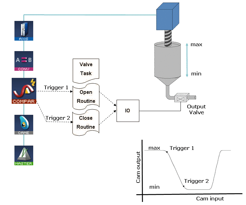
Figure 1: Comparator Used to Control a Valve on a Filler Mechanism
Examples: Comparator Functions
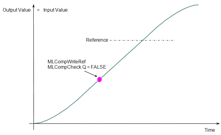
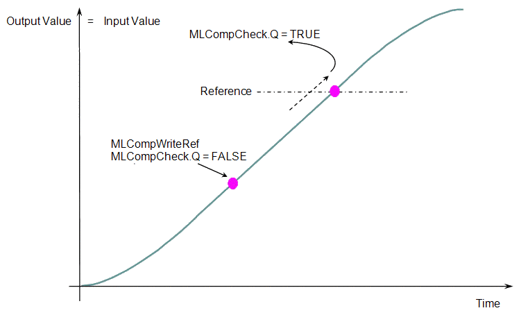
When you call the MLCompWriteRef function (Figure 2), the output for MLCompCheck becomes TRUE (Figure 3) as soon as the input value reaches the reference.
|
|
|
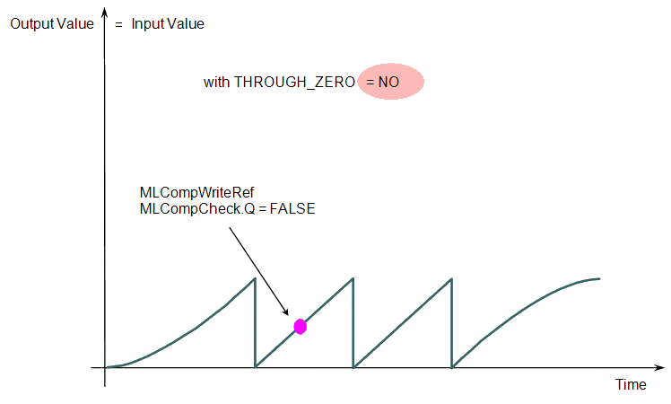
The same function can also be called for a cyclic input value. (Figure 4 and Figure 5)
|
|
|
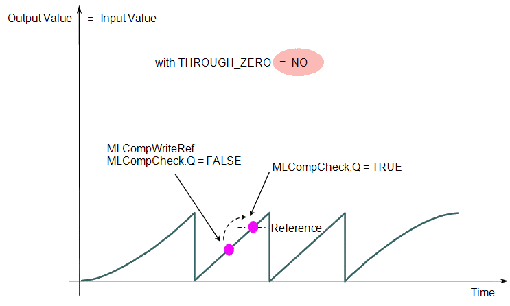
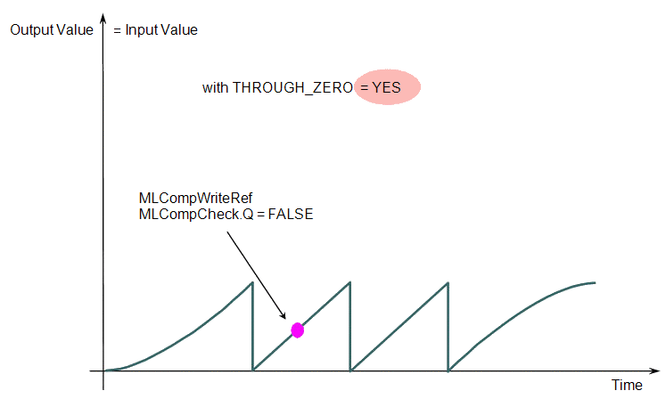
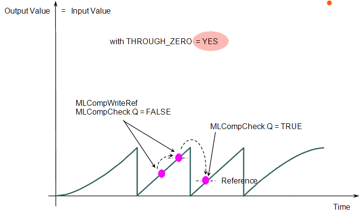
When the THROUGH_ZERO parameter is set to YES (Figure 6), the output for MLCompCheck becomes TRUE (Figure 7) as soon as the input value reaches the reference, but not before it has passed through zero.
|
|
|
Associated Data
- OutputValue: Output value of the data flows.
- IsReady: Boolean set to TRUE when the pipe block is ready.


