


 Feedback # View
Each feedback device has its own view for detailed configuration. This view is used to set up your system to match the proper feedback device. By default, the drive assigns Feedback 1 to Axis 1, Feedback 2 to Axis 2, and uses the Auto Identify setting to detect feedback devices. This setting allows the drive to test the feedback device to see if it is a recognized plug and play device. If the drive recognizes the device, then all parameters for that device and motor are loaded into the drive. Both the feedback and the motor information are now present in the drive and the system is operable.
If the feedback is a non-plug and play device, then you can choose from the list of supported devices in the Feedback Selection list and enter the feedback settings manually. The following sections describe each supported device available in the Feedback Selection list and the input information required to configure each device.
FB#.INFO can be used to read additional information about the feedback when it is available.
Scaling For Use Within WorkBench
| Feedback linked to an axis | Feedback not linked to an axis |
|---|---|
|
The units and scaling of feedback linked to an axis are not configurable because the axis defines the units and gearing values which are set up in the Units view (see Selecting Units for Your Application). The default settings provide scaling in degrees. One revolution of rotary feedback in the positive direction advances the position by 360 degrees. |
Scaling of feedback that is not linked to an axis uses the settings found in the Monitoring section of this view. This is typically used to send the feedback position to an external controller via a fieldbus. |
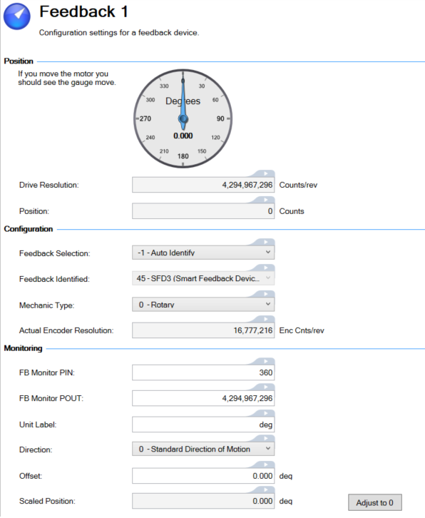
Position
This section of the Feedback view provides the current state of the feedback device.
| Element | Description | Parameter |
|---|---|---|
| Meter |
Provides live data showing the relative position within a revolution of the feedback device. The Mechanic Type setting determines the meter type.
|
|
| Drive Resolution | Displays the resolution used for the device. Rotary devices are counts / mechanical revolution, linear devices are counts / pole. | FB#.PRES |
| Position | Displays the raw position of the feedback device in counts. | FB#.P |
Configuration
This parameter reports the actual encoder resolution of the feedback device. The drive calculates the FB#.RES value based on the encoder characteristics. It is provided in encoder counts/rev for rotary encoders and encoder counts/mm for linear encoders.
| Element | Description | Parameter |
|---|---|---|
| Feedback Selection | Specify the type of feedback automatically or manually. See Feedback Types below for a description of each type. | FB#.SELECT |
| Feedback Identified | This parameter is set according to FB#.SELECT on drive power up if FB#.SELECT is not –1. Otherwise the parameter value is read from the drive memory. | FB#.IDENTIFIED |
| Mechanic Type | Select whether the feedback is a rotary (0) or linear (1) encoder. | FB#.MECHTYPE |
| Encoder Resolution | Configure the number of lines per revolution for rotary encoders or the line pitch (nm/line) for linear encoders. |
|
| Actual Encoder Resolution |
This parameter reports the actual encoder resolution of the feedback device. The drive calculates the FB#.RES value based on the encoder characteristics. It is provided in encoder counts/rev for rotary encoders and encoder counts/mm for linear encoders. |
FB#.RES |
| Multi-turn Sensor Bits | Number of multi-turn bits used for BiSS encoders when used in rotary motors. | FB#.MULTITURNBITS |
| Single-turn Sensor Bits | Number of single turn bits used for BiSS rotary encoders. | FB#.SINGLETURNBITS |
| Feedback Poles | Sets the number of individual poles in a Resolver feedback device. This variable is used for the commutation function, as well as for velocity feedback scaling, and represents the number of individual poles (not pole pairs). | FB#.POLES |
| Transformation Ratio | Sets the Resolver nominal transformation ratio. It affects the resolver excitation output amplitude. | FB#.RESKTR |
| Phase Lag | Sets the electrical degrees of phase lag in the Resolver. | FB#.RESREFPHASE |
If the feedback is a non-plug and play device, then you can choose from the list of supported devices in the Feedback Selection list and enter the feedback settings manually. The following sections describe each supported device available in the Feedback Selection list and the input information required to configure each device.
FB#.INFO can be used to read additional information about the feedback when it is available.
Monitoring
-
- These fields are only used for situations where the feedback is not connected to an axis. When feedback is connected to an axis, scaling is set up in the Units view.
This section of the view provides for a way to see scaled feedback values. These fields are used when you want to see the feedback position in units other than raw counts. See Scaled Feedback for details on how the Scaled Position is calculated.
| Element | Description | Default | Parameter |
|---|---|---|---|
| FB Monitor PIN | The numerator of the Scaled Position ratio. | 360 | FB#.SCALED.PIN |
| FB Monitor POUT | The denominator of the Scaled Position ratio. | 4,294,967,296 | FB#.SCALED.POUT |
| Unit Label | Descriptive text that is printed with the Scaled Position. Typically used to indicate units. | deg | FB#.SCALED.LABEL |
| Direction | Sets the direction of the Scaled Position, relative to the position feedback FB#.P. | 0 | FB#.SCALED.DIR |
| Offset |
Sets the offset adjustment for Scaled Position using the same scaling and units. |
0.000 | FB#.SCALED.OFFSET |
| Scaled Position | The scaled feedback position. See Scaled Feedback for details on the calculation. | N/A | FB#.SCALED.P |
| Adjust to 0 | The Adjust to 0 (zero) button sets the Scaled Position value to zero. | N/A | FB#.SCALED.ZERO |
Jump to a section about Feedback:
- Feedback Views
- Feedback Configuration
- Feedback Methods
- Smart Feedback Adapter (SFA)
- Non-Plug and Play Feedback Devices


