


Feedback Types
| Value | Type | Description | ||||||||||||||||
|---|---|---|---|---|---|---|---|---|---|---|---|---|---|---|---|---|---|---|
| -1 | Auto Identify | The default setting for Feedback 1 and Feedback 2, Auto Identify is used to determine if a plug and play device is available. If a plug and play device is available, the FB#.IDENTIFIED keyword indicates the feedback device is detected and FB#.RES is updated with the resolution of the detected feedback. | ||||||||||||||||
| 1 | No Encoder | This setting can be used if no feedback device is connected to the associated feedback connector. | ||||||||||||||||
| 10 | Incremental Encoder with Halls |
Incremental encoders are available in a variety of line counts. When selecting an incremental encoder option, the encoder resolution must be entered into the Actual Encoder Resolution field or by setting FB#.ENCLINES. The units for this field are in lines per revolution. Wake and Shake is enabled when using incremental encoders without Halls sensors.
|
||||||||||||||||
| 11 | Incremental Encoder without Halls | |||||||||||||||||
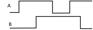
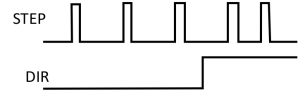
| 13 | Step / Direction |
This mode is intended to be used by controllers to provide an Electronic Gearing source signal. The A line pulses for each step and the B line indicates the direction. Actual Encoder Resolution (FB#.ENCLINES) is used to configure the number of pulses per revolution.
|
||||||||||||||||
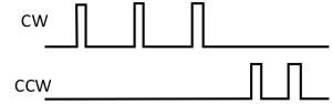
| 14 | CW / CCW |
As with Step/Direction, this mode is intended to be used as an Electronic Gearing source signal. The A line controls pulses in a clockwise direction and the B line control pulses in a counter-clockwise direction. Actual Encoder Resolution (FB#.ENCLINES) is used to configure the number of pulses per revolution.
|
||||||||||||||||
| 20 | Sine Encoder with Halls |
A sine-cosine uses a sine wave to indicate rotation. As with the incremental encoder, the line count is entered in the Actual Encoder Resolution field or by setting FB#.ENCLINES. The actual resolution is much higher than the encoder line setting from measuring the analog signal. Wake and Shake is enabled when using sine encoders without Halls sensors. |
||||||||||||||||
| 21 | Sine Encoder without Halls | |||||||||||||||||
| 30 | EnDat 2.1 - Analog |
EnDat uses a sine encoder to indicate position with an analog signal. |
||||||||||||||||
| 31 | EnDat 2.2 - Digital |
EnDat is compatible with both digital only and sin/cos analog signals. However, some EnDat models only support digital only signals. |
||||||||||||||||
| 34 | BiSS Mode C - Digital |
These feedback devices are all digital. See manufacturer specs for more information. |
||||||||||||||||
| 36 | SSI |
Select the type of SSI (Synchronous Serial Interface) device. The SSI Type field defines the manufacturer model and protocol used. The protocols differ in the data format of the serial position bits, and may contain special configuration and flag bits.
See also FB#.SSITYPE. |
||||||||||||||||
| 40 | Resolver |
The resolver feedback is an analog signal. When selecting the resolver option, the resolver specific parameters phase lag, transformation ratio, and feedback poles are set for AKM motors.
|
||||||||||||||||
| 41 | SFD (Smart Feedback Device) | Smart Feedback Device (SFD) is Kollmorgen's most popular plug and play device. SFD allows for quick and easy setup from the Auto mode, which automatically configures the drive with the motor and feedback parameters. SFD3 only requires 2 wires while SFD requires 4 wires. | ||||||||||||||||
| 45 | SFD3 (Smart Feedback Device Gen3) | |||||||||||||||||
| 46 | HIPERFACE DSL |
These feedback devices are all digital. See manufacturer specifications for more information. |
Jump to a section about Feedback:
- Feedback Views
- Feedback Configuration
- Feedback Methods
- Smart Feedback Adapter (SFA)
- Non-Plug and Play Feedback Devices


