


SDI (Safe Direction)
SDIn/SDIp description for drive option Functional Safety 3.
|
SDIp |
SDIn |
|
|---|---|---|
|
|
|
|
Description
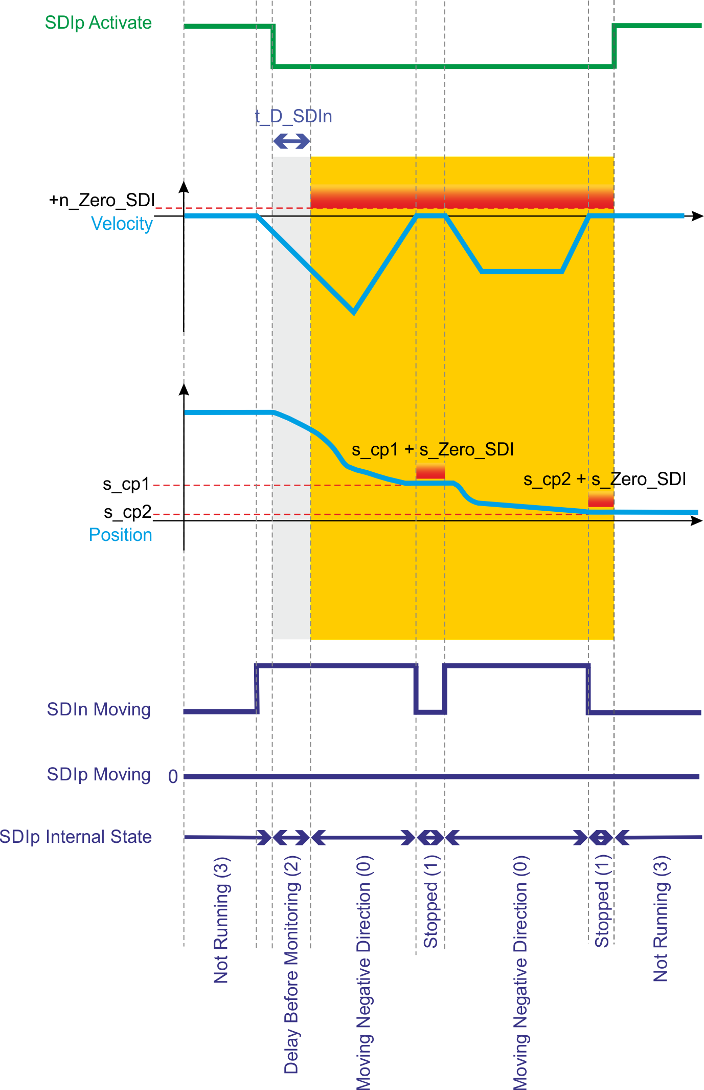
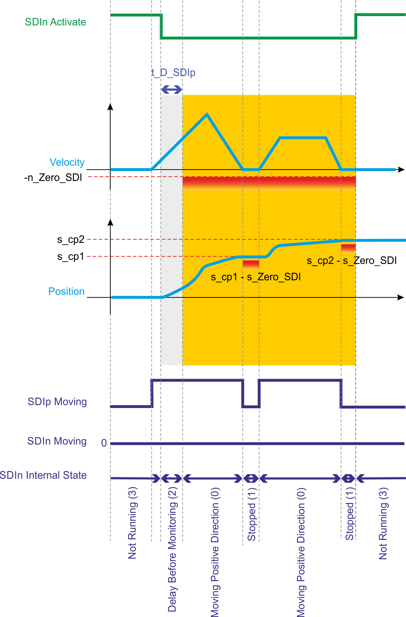
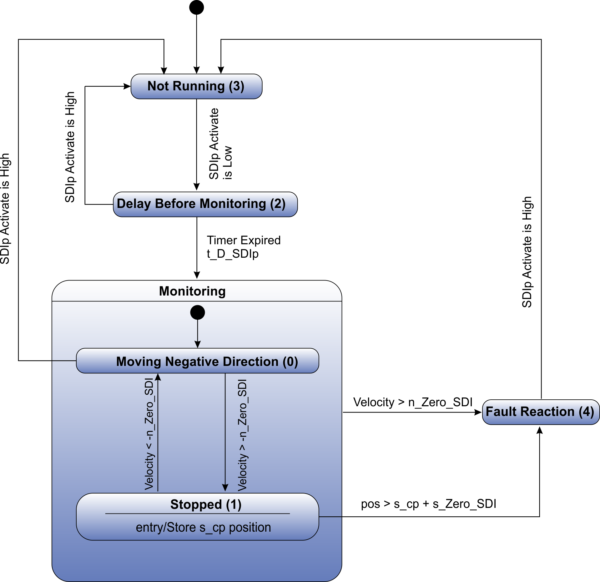
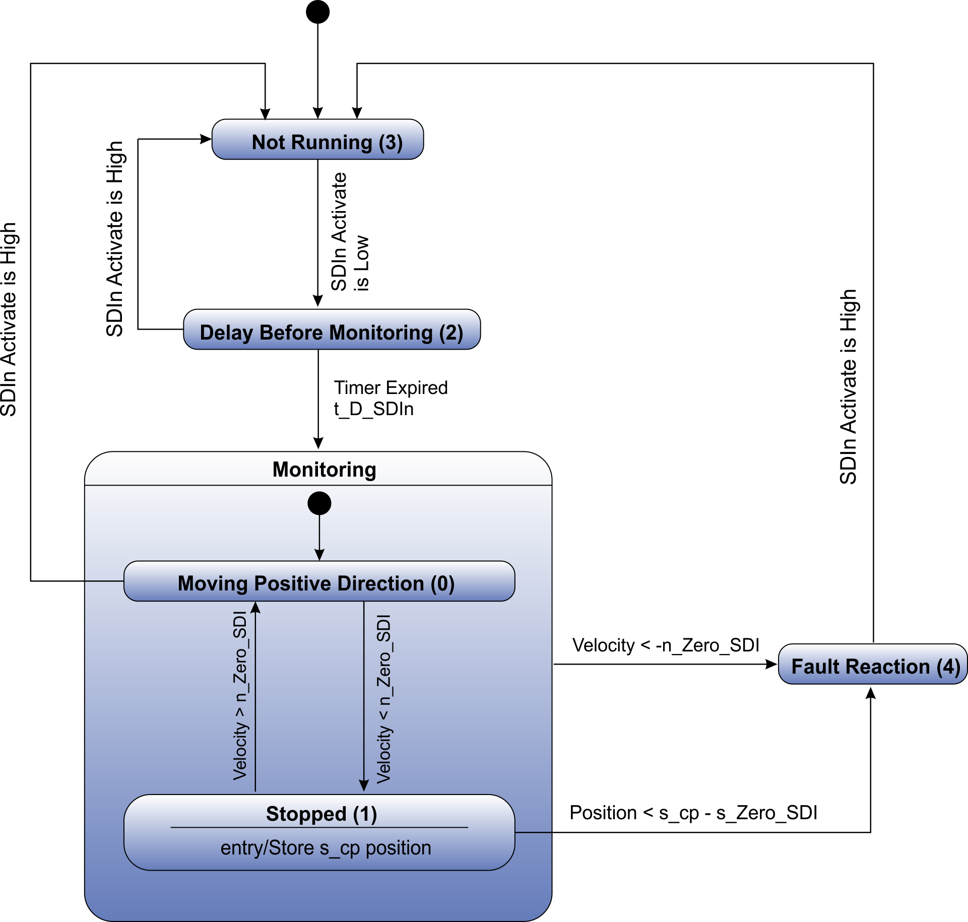
SDI monitors the direction of movement and activates a configurable fault reaction when a violation occurs. SDI consists of two sub-functions: SDIp (for positive direction) and SDIn (for negative direction). Both functions share
- the same position window paramater s_Zero_SDI,
- the same velocity limit parameter n_Zero_SDI and
- the same configurable fault reaction.
However, they have their own sources of activation and their own delay before monitoring (t_D_SDIp and t_D_SDIn):
- When SDIp is activated, the safety module prevents motion in the positive direction. The motion can either be in the negative direction or be stopped.
- When SDIn is activated, the safety module prevents motion in the negative direction. The motion can either be in the positive direction or be stopped.
- If both functions are activated at the same time, the motion must be stopped.
Number of Instances
One instance per axis.
Function Input / Output Variables
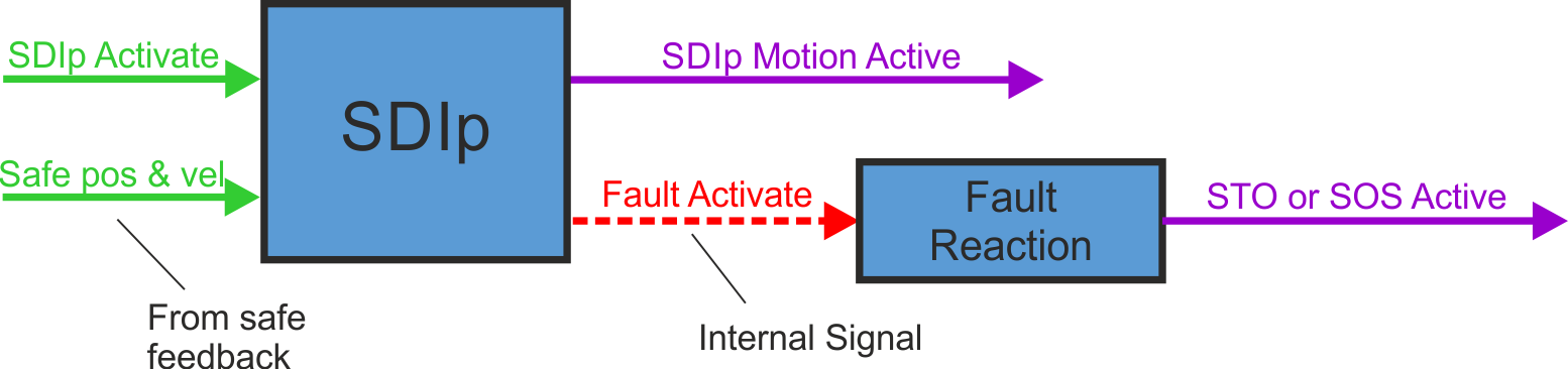

Inputs
- SDIp Activate can be triggered by FSoE or safe digital inputs (must be mapped)
- SDIn Activate can be triggered by FSoE or safe digital inputs (must be mapped)
- Safe pos & vel: position and velocity signal from safe feedback
Outputs
- SDIp Motion Active: indicates whether the axis is moving in the positive direction
- SDIn Motion Active: indicates whether the axis is moving in the negative direction
- Fault Activate: activate fault reaction
Activation
|
Activation by FSoE |
|
|
Activation by safe digital inputs |
|
Timing
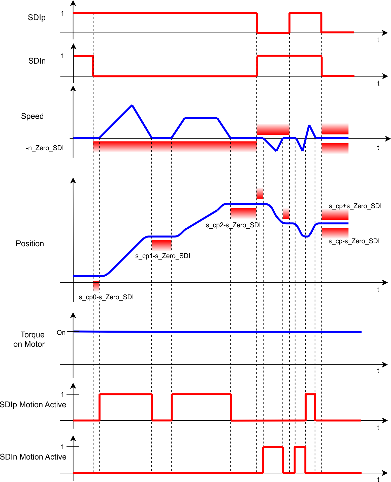
s_cp defines the safe position which is taken while the function activates. It is used to compute the range of allowed position values that the axis can take while the position monitoring is activated. The range is computed by adding or substracting s_Zero_SDI to/from the parameter s_cp.
Related Parameters
Safety parameters
|
Name |
Variables |
Default |
Parameter |
|---|---|---|---|
|
Function Activation |
- |
0 (Never active) |
|
|
Safe Input SDIp |
- |
0 (Not used) |
|
|
FSoE SDIp |
- |
0 (Not used) |
|
|
Safe Input SDIn |
- |
0 (Not used) |
|
|
FSoE SDIn |
- |
0 (Not used) |
|
|
Position Zero Window |
s_Zero_SDI |
1 (Pos user units) |
AXIS#.SAFEPARAM.SDI.POSZEROWINDOW; usable value range depends on used encoder type, see limitations: |
|
Velocity Zero Window |
n_Zero_SDI |
1 (Vel user units) |
|
|
Time Delay Monitoring SDIp |
t_D_SDIp |
1 ms |
|
|
Time Delay Monitoring SDIn |
t_D_SDIn |
1 ms |
|
|
Fault Reaction |
- |
1 (STO) |
Diagnostic parameters
| Name |
Variables |
Default |
Parameter |
|---|---|---|---|
|
SDIp Moving |
- |
- |
|
|
SDIp Function Internal Status |
- |
- |
|
|
SDIn Moving |
- |
- |
|
|
SDIn Function Internal Status |
- |
- |
State Diagrams
|
SDIp |
SDIn |
|
|---|---|---|
|
|
|
|
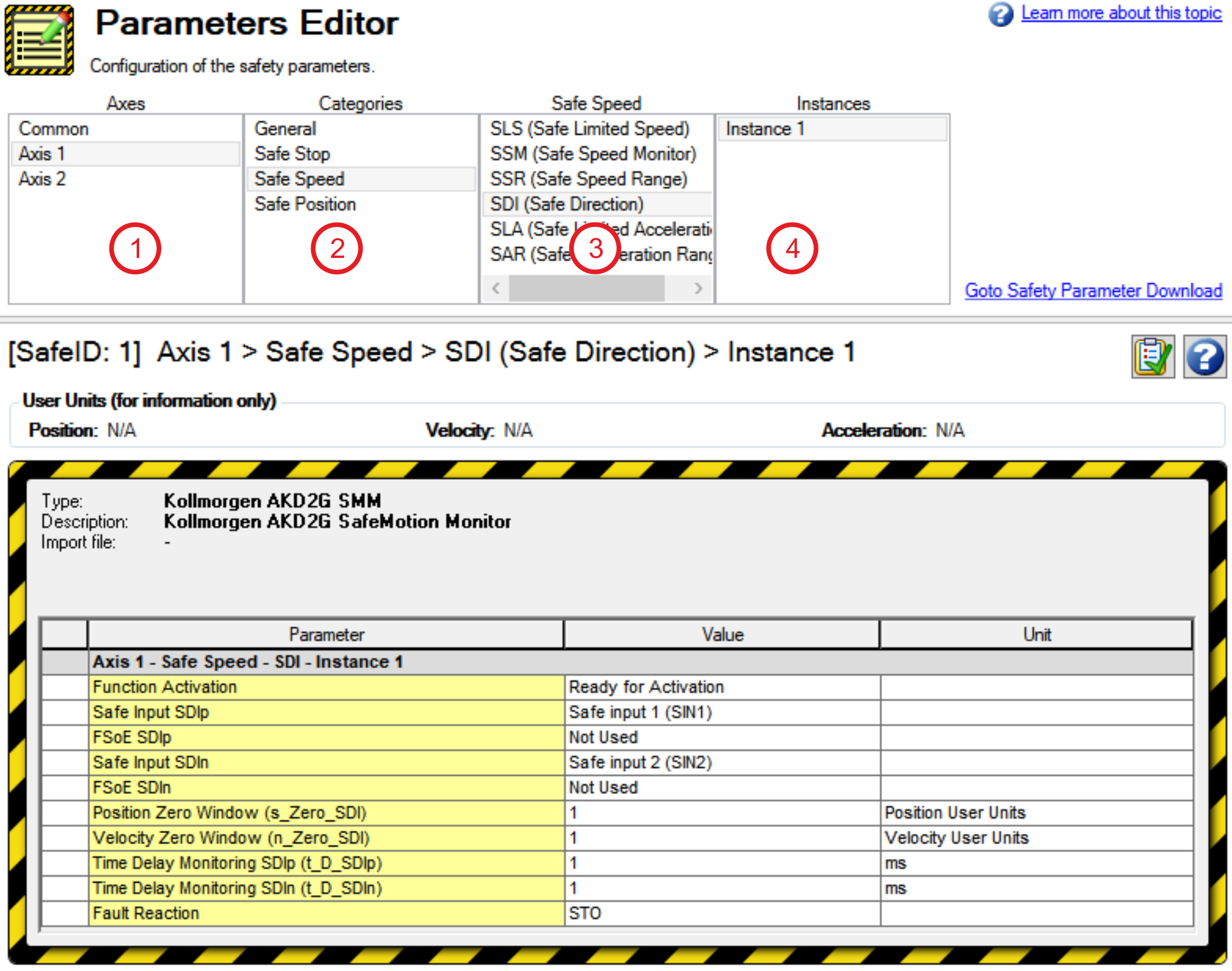
Setup in WorkBench
Select the drive and open the Safety Parameterization view (see "Parameters Editor").
Choose the axis (1), category (2), SDI function (3) and the instance number (4).
Fault Reaction / Failure Messages
SDI has a configurable fault reaction. STO is used by default but can be replaced by SS1 Instance 1 or SS2 Instance 1. When the fault reaction is activated, the internal states of SDI (AXIS#.SAFE.SDIp.INTERNALSTATE and AXIS#.SAFE.SDIn.INTERNALSTATE) are set to failed state (4).
Safety State / Status Signals
The signals AXIS#.SAFE.SDIn.MOTIONACTIVE and AXIS#.SAFE.SDIp.MOTIONACTIVE can be monitored by safe digital outputs with OSSD pulses (see "OSSD"). The status signals must be mapped to the safe digital outputs. Two outputs can be combined to a dual channel output. For parameter description refer to Functional Safety Parameter Reference.
Safety Properties
Refer to (➜ # 1, Safety Properties Overview).