


SLI (Safely Limited Increment)
SLI description for drive option Functional Safety 3.
Description
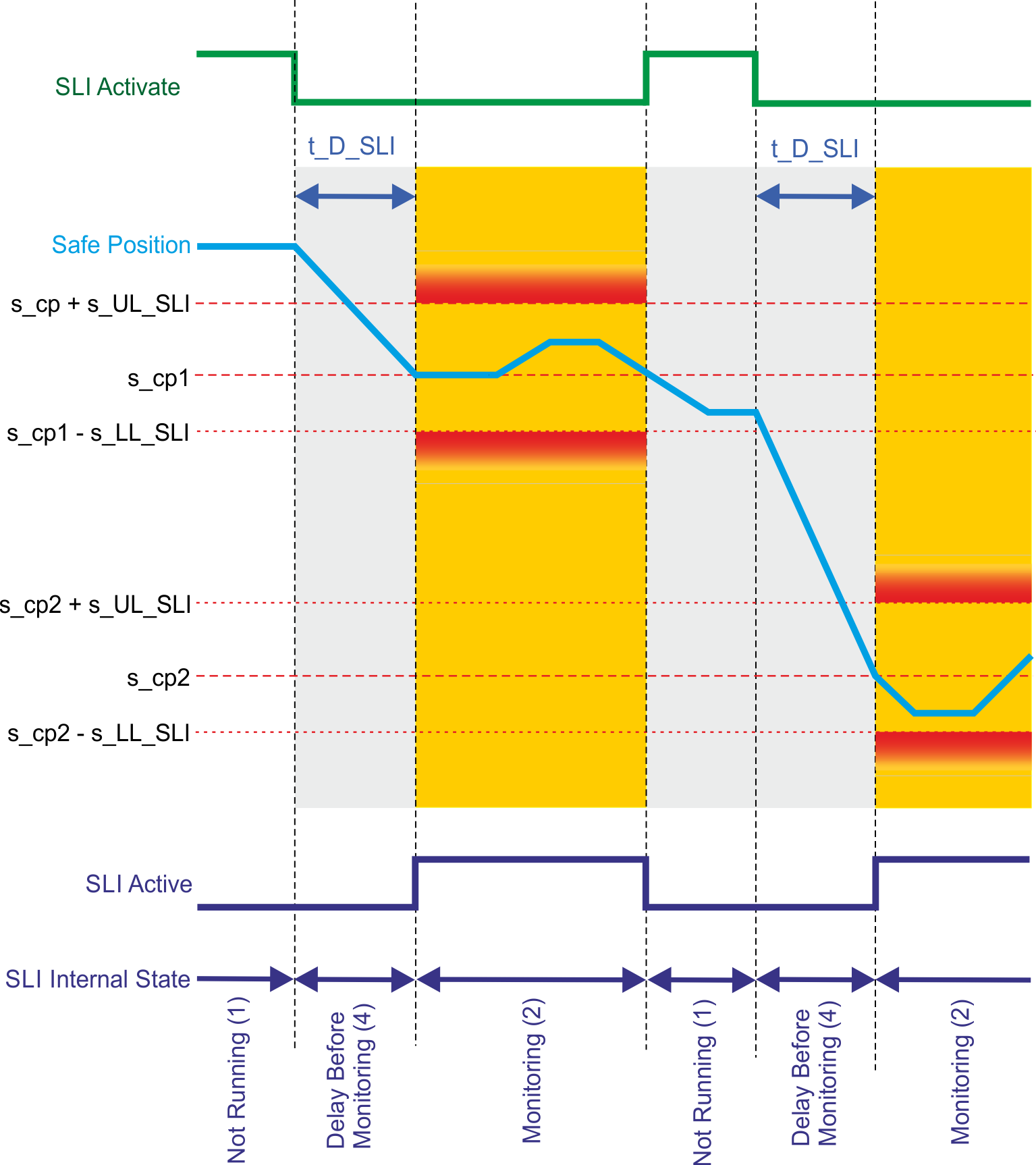
SLI, when active, monitors the incremental position and ensures that it stays in a position window. This position window is defined as follows:
The position is taken at the time where the function gets activated. For the upper limit the parameter s_UL_SLI is added. For the lower limit the parameter s_LL_SLI is substracted. If the position leaves the position window a configurable fault reaction will be activated.
If necessary, the start of monitoring can be delayed by using the configurable parameter t_D_SLI.
Number of Instances
Three instances per axis.
Function Input / Output Variables
Inputs
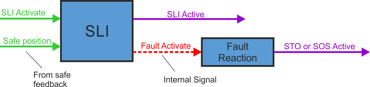
- SLI Activate can be triggered by FSoE or safe digital inputs (must be mapped)
- Safe position: position signal from safe feedback
Outputs
- SLI Active: logical status of the SLI function
- Fault Activate: activate fault reaction
Activation
|
Activation by FSoE |
|
|
Activation by safe digital inputs |
|
Timing
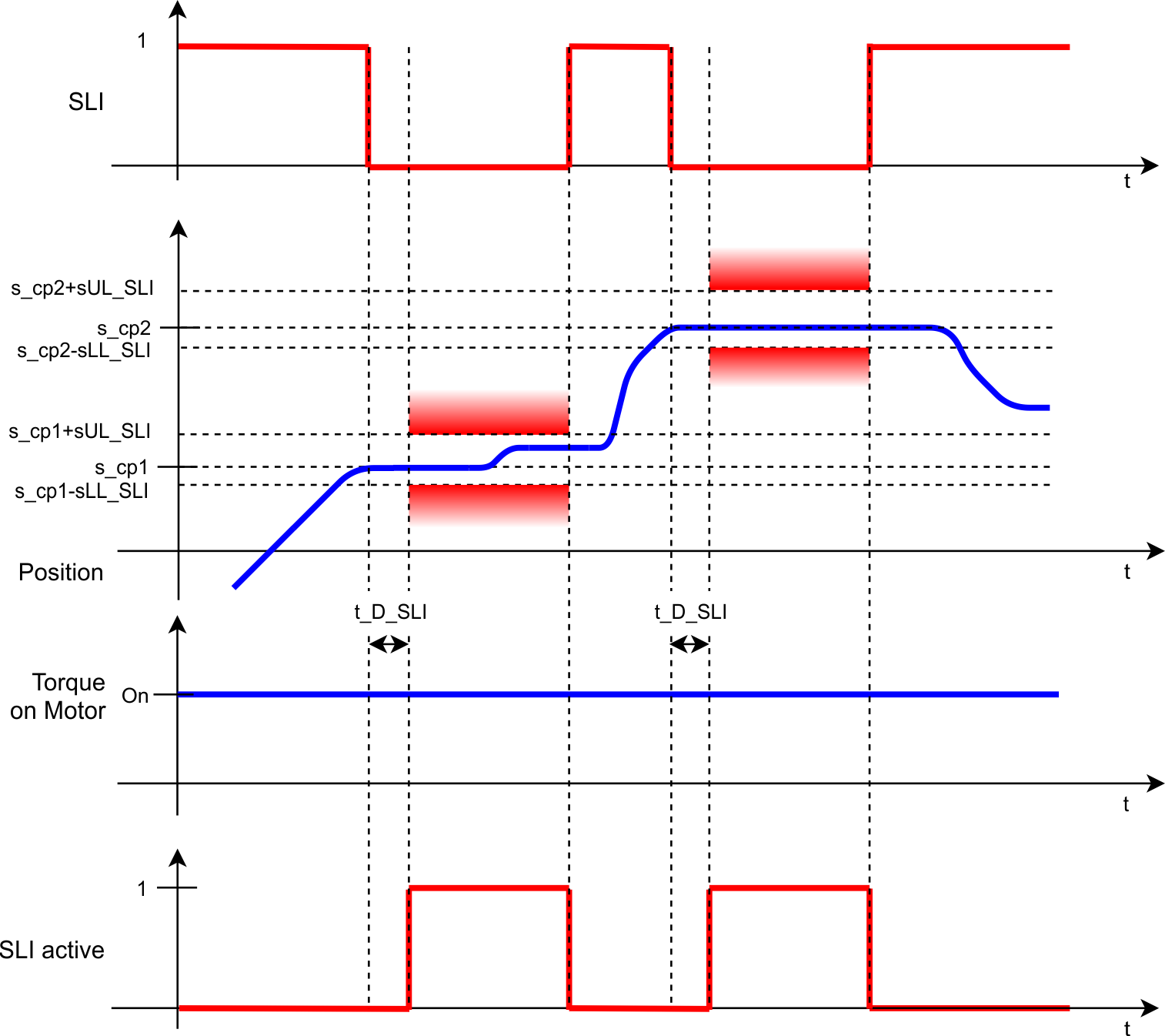
s_cp defines the safe position which is taken while the function gets activated. It is used to compute the range of allowed position values that the axis can take while the position monitoring is activated. The range is computed by adding or subtracting s_UL_SLI/s_LL_SLI to/from the parameter s_cp.
Related Parameters
Safety parameters
|
Name |
Variables |
Default |
Parameter |
|---|---|---|---|
|
Function Activation |
- |
0 (Never active) |
|
|
Safe Input |
- |
0 (Not used) |
|
|
FSoE |
- |
0 (Not used) |
|
|
Position Relative Upper Limit |
s_UL_SLI |
1 (Pos user units) |
AXIS#.SAFEPARAM.SLI_#.POSRELUPPERLIMIT; usable value range depends on used encoder type, see limitations: |
|
Position Relative Lower Limit |
s_LL_SLI |
1 (Pos user units) |
AXIS#.SAFEPARAM.SLI_#.POSRELLOWERLIMIT; usable value range depends on used encoder type, see limitations: |
|
Time Delay Monitoring |
t_D_SLI |
0 ms |
|
|
Fault Reaction |
- |
1 (STO) |
Diagnostic parameters
| Name |
Variables |
Default |
Parameter |
|---|---|---|---|
|
Function Active Status |
- |
- |
|
|
Function Internal Status |
- |
- |
State Diagram
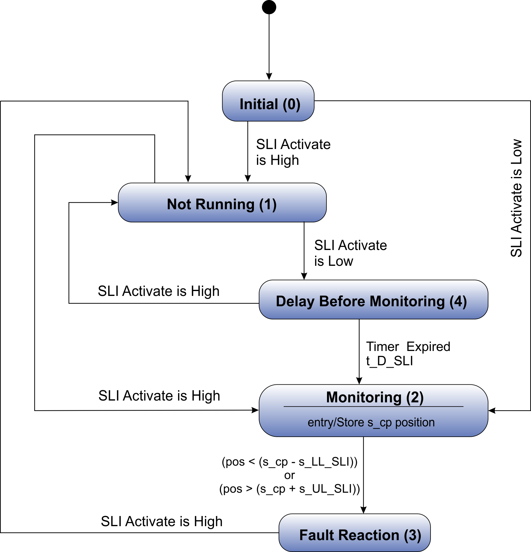
SLI is active if internal state is "Monitoring (2)" or "Fault reaction (3)".
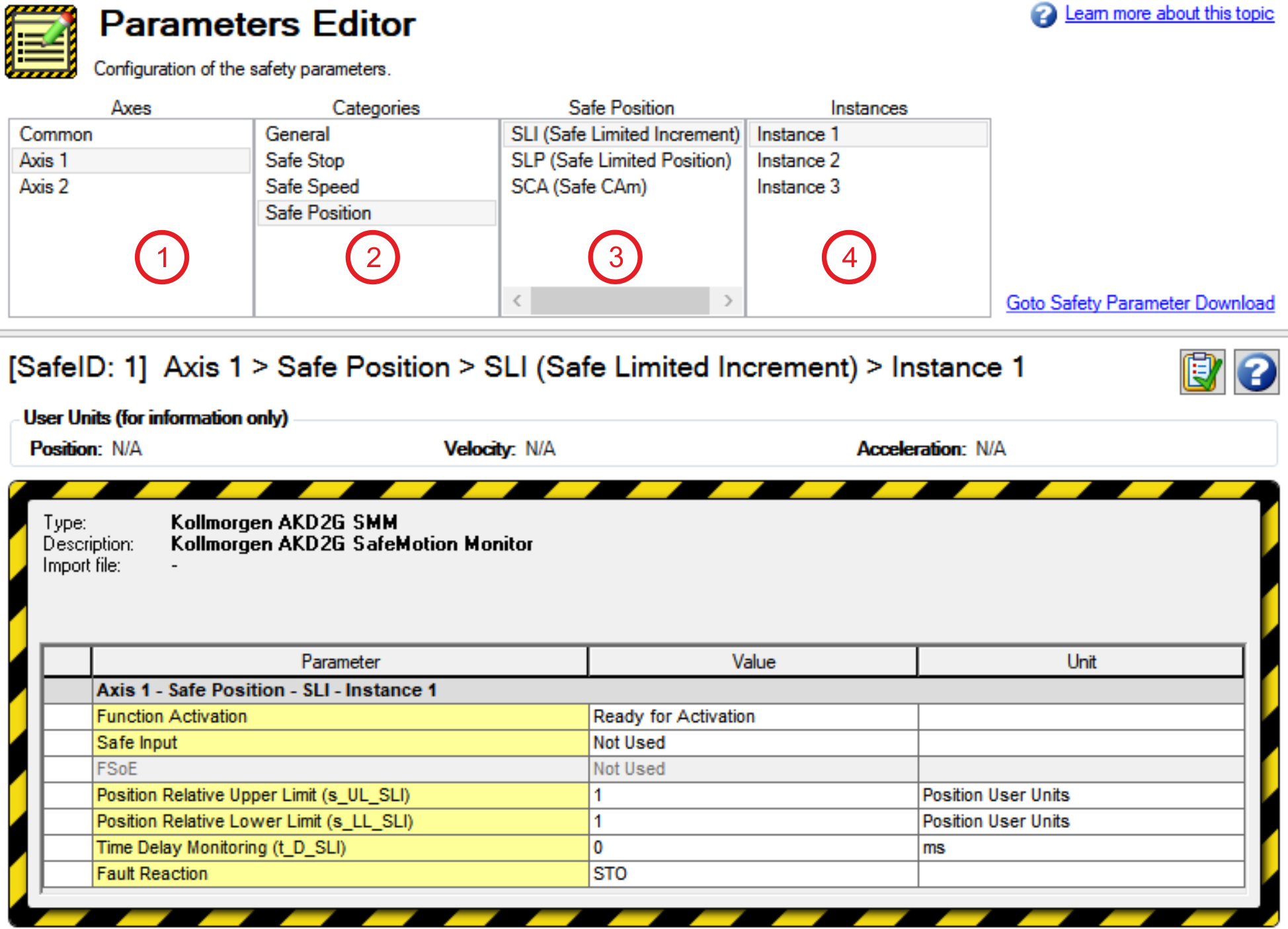
Setup in WorkBench
Select the drive and open the Safety Parameterization view (see "Parameters Editor").
Choose axis (1), category (2), SLI function (3) and the instance number (4).
Fault Reaction / Failure Messages
SLI has a configurable fault reaction. STO is used by default but can be replaced by SS1 Instance 1 or
SS2 Instance 1. When the fault reaction is activated, SLI remains active and the internal state
(AXIS#.SAFE.SLI_#.INTERNALSTATE) is set to failed state (3).
Safety State / Status Signals
The signal AXIS#.SAFE.SLI_#.ACTIVE can be monitored by safe digital outputs with OSSD pulses (see "OSSD"). The status signal must be mapped to the safe digital output. Two outputs can be combined to a dual channel output. For parameter description refer to Functional Safety Parameter Reference.
Safety Properties
Refer to (➜ # 1, Safety Properties Overview).