 Enable/Disable
Enable Modes
The AKD offers several options for hardware and software enables, as well as safe torque![]() Torque is the tendency of a force to rotate an object about an axis. Just as a force is a push or a pull, a torque can be thought of as a twist off (STO) to cover a variety of conditions.
Torque is the tendency of a force to rotate an object about an axis. Just as a force is a push or a pull, a torque can be thought of as a twist off (STO) to cover a variety of conditions.
Hardware Enable Mode
The AKD has two hardware enable methods. These methods are controlled by DRV.HWENMODE. Mode 0 allows for the drive to enable and clear faults on the rising edge![]() A rising edge is the transition of a digital signal from low to high. It is also called positive edge of the hardware enable input. Mode 1 will NOT clear any faults on the rising edge of the hardware enable input, allowing the review of any current faults for manual clearing.
A rising edge is the transition of a digital signal from low to high. It is also called positive edge of the hardware enable input. Mode 1 will NOT clear any faults on the rising edge of the hardware enable input, allowing the review of any current faults for manual clearing.
Software Enable Default
In addition, the Software Enable has two methods for enabling the AKD. These are controlled by DRV.ENDEFAULT. Default 0 leaves the software in the disabled state upon start-up. Default 1 enables the software upon start-up.
Disable Modes
Use DRV.DISMODE to select the method for stopping the drive when DRV.DIS (software disable) is commanded or upon a fieldbus command.

Mode 0: Immediately disable drive.
With this condition, the drive will immediately disable the power stages and the driven motor will either coast to a stop or in the case of a vertical or overhung load axis, will fall abruptly. If a brake is present, the brake will be applied according to MOTOR.BRAKEIMM and MOTOR.TBRAKEAPP . Using Digital Input mode 13, you can achieve a controlled stop as described in Mode 2.
Mode 1: Dynamic Brake to a stop.
In this situation, the drive will use the dynamic brake feature and stop motion quickly, and then disable the power stage. In most cases, the driven motor will stop quickly (pending the joules available and load circumstances). In the case of an overhung or vertical load, the driven motor will attempt to stop, but then will continue to allow the load to fall if no measures have been taken to secure the load.
Mode 2: Controlled stop, then disable.
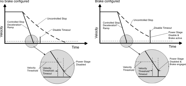
In this mode, a controlled stop will take place based on a variety of parameters that you set. First, the driven motor will decelerate at a controlled rate (CS.DEC ) until one of two things happens. 1) The motor reaches the velocity limit set (CS.VTHRESH ) for a period of time (CS.TO ), or 2) The drive emergency time out is reached (DRV.DISTO ). Once either of these cases is reached, the power stage will be disabled (and brake applied if present)
Mode 3: Controlled stop, then dynamic brake.
Similar to Mode 2, the motor will decelerate at a controlled rate (CS.DEC) until CS.VTHRESH is reached for a period of time (CS.TO). The drive will then dynamically brake and disable under the same conditions as described in Mode 1.
The Disable Timeout Setting determines the amount of time the drive will follow the disable mode before it deactivates the drive regardless of method chosen and alerts with an Emergency Timeout Fault.
All disable modes operate based on the type of disable command received. Any critical faults, hardware disable, or STO disable immediately turn off the power stage, and the motor will coast or free fall, depending on how the motor is secured.
Device Status
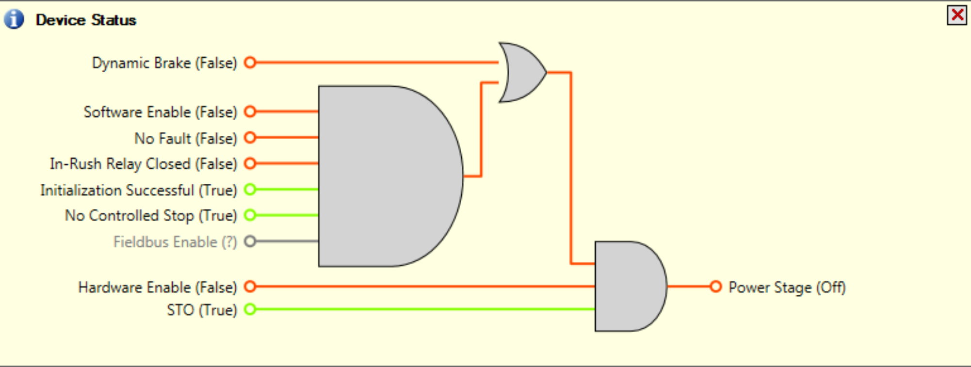
The Device Status area is displayed when clicking the "Axis Active/Axis inactive" button at the bottom of WorkBench:

It includes a graphical representation of drive active status with different sets of inputs. If the input or output is enabled, then it is shown in green; if the input or output is disabled, then it is shown in red. The inputs to the OR and & (AND) gates identify which conditions are true (green) or false (red) and follow the normal logic for & (AND) and OR gates. This diagram is useful for finding which input may be preventing the drive from being enabled.
The overall status that is reflected by this diagram indicates the value of the DRV.ACTIVE keyword. In addition, the state of the inputs in the diagram (i.e. Software enable, Hardware enable) are indicated by the Keyword DRV.DISSOURCES .

Controlled Stop
The Controlled Stop area displays values for parameters associated with controlled stop.
| Button or Dialog Box |
Description |
Parameter |
|---|---|---|
|
Velocity Threshold |
Sets the velocity threshold for controlled stop process. |
CS.VTHRESH |
|
Velocity Threshold Timeout |
Sets the velocity threshold, which is the time value for the drive velocity to be within CS.VTHRESH before the drive disables |
CS.TO |
|
Deceleration |
Sets the deceleration value for the controlled stop process. |
CS.DEC |
|
Control stop Input |
Displays the list of digital inputs configured to controlled stop mode separated by ','. When no controlled stop mode is configured, this box displays the message: No CS Input Configured. The Configure Input link opens the Digital I/O screen where you can configure the controlled stop mode. |
More/Less Button
The More button reveals the status diagram for the controlled stop configuration. It also displays the block diagram for the control stop. Two block diagrams are available: one for a brake fitted and another for no brake.
Control stop status diagram

Controlled Stop Block Diagram


