Axis Parameters
Boolean Parameters
This table is a list of Boolean supported parameters.
These parameters are read and written by the function blocks MC_ReadBoolPar and MC_WriteBoolPar.
|
ID |
Parameter |
Name |
R/W |
Update Rate Type |
Description |
|---|---|---|---|---|---|
|
1011 |
MC_AXIS_PARAM_IN_POSITION |
Axis In-Position |
Read-only |
|
|
|
1013 |
MC_AXIS_PARAM_DRIVE_WARNING |
Drive Warning |
Read-only |
Drive Warning Status. 1 |
|
|
1025 |
MC_AXIS_PARAM_REGIST_GOOD |
Good Registration Mark Occurred |
Read-only |
|
|
|
1026 |
MC_AXIS_PARAM_REGIST_BAD |
Bad Registration Mark Occurred |
Read-only |
|
|
|
1027 |
MC_AXIS_PARAM_FI_OCCURRED |
Read-only |
Deprecated Behavior
|
||
|
1033 |
MC_AXIS_PARAM_APPLY_SUPERIMPOSED_DISTANCE |
Apply Superimposed Distance |
Read / Write |
The default value for this parameter is FALSE.
Param 1033 = False
Param 1033 = True |
Non-Boolean Parameters
This table is a list of non-Boolean parameters currently supported.
These parameters are read and written by the function blocks MC_ReadParam and MC_WriteParam.
|
ID |
Parameter |
Name |
R/W |
Update Rate Type |
Description |
|---|---|---|---|---|---|
|
1 |
Command Position |
Read-only |
|
||
|
10 |
MC_AXIS_PARAM_ACT_VEL |
Actual Velocity |
Read-only |
|
|
|
11 |
MC_AXIS_PARAM_CMD_VEL |
Command Velocity |
Read-only |
|
|
|
1000 |
MC_AXIS_PARAM_PHASE_SHIFT |
Phase Shift |
Read-only |
|
|
|
1001 |
MC_AXIS_PARAM_SUPERIMPOSED_DISTANCE |
Superimposed Distance |
Read-only |
|
|
|
1002 |
MC_AXIS_PARAM_MASTER_OFFSET |
Master Offset |
Read / Write |
|
|
|
1003 |
MC_AXIS_PARAM_SLAVE_OFFSET |
Slave Offset |
Read / Write |
|
|
|
1004 |
MC_AXIS_PARAM_MOVE_TYPE_ACTIVE |
Active Move Type |
Read-only |
The active move type. See Move Types. |
|
|
1005 |
MC_AXIS_PARAM_MOVE_TYPE_NEXT |
Next Move Type |
Read-only |
The queued (next) move type. See Move Types. |
|
|
1006 |
Position Error |
Read-only |
Position error in user units. |
||
|
1007 |
MC_AXIS_PARAM_FEEDBACK_LAST |
Raw Feedback |
Read-only |
|
|
|
1008 |
MC_AXIS_PARAM_ROLLOVER_POSITION |
Rollover |
Read / Write |
In particular: {equation}NewPosition = OldPosition * (New Rollover) / (Old Rollover){/equation}.
|
|
|
1009 |
MC_AXIS_PARAM_VELCOMP_FACTOR |
Velocity Compensation Factor |
Read / Write |
|
|
|
1010 |
MC_AXIS_PARAM_VELCOMP_FILTER |
Velocity Compensation Filter |
Read / Write |
|
|
|
1012 |
MC_AXIS_PARAM_IN_POSITION_BAND |
Read / Write |
The bandwidth about the command position to determine the state of the in-position flag. 2 |
||
|
1014 |
MC_AXIS_PARAM_DRIVE_STATUS |
Drive Status |
Read-only |
|
|
|
MC_AXIS_PARAM_UU_FB_RATIO_NUM |
User Unit to feedback unit ratio numerator |
Read-only |
|
||
|
MC_AXIS_PARAM_TORQUE_ACTUAL |
Read-only |
|
|||
|
1017 |
MC_AXIS_PARAM_BUS_ADDRESS |
Drive Address |
Read-only |
|
|
|
1018 |
MC_AXIS_PARAM_SENSOR_DELAY |
Read / Write |
Compensation for Physical sensor |
||
|
1019 |
MC_AXIS_PARAM_INTERP_CMD_POS |
Interpolated Command Position |
Read-only |
|
|
|
1020 |
MC_AXIS_PARAM_INTERP_CMD_VEL |
Interpolated Command Velocity |
Read-only |
|
|
|
1021 |
MC_AXIS_PARAM_REGIST_COMP |
Registration Compensation |
Read-only |
|
|
|
1022 |
MC_AXIS_PARAM_REGIST_DIST |
Distance Between the Last Two Good Registration Marks |
Read-only |
|
|
|
1023 |
MC_AXIS_PARAM_REGIST_GOOD_CNT |
Number of Consecutive Good Registration Marks |
Read / Write |
|
|
|
1024 |
MC_AXIS_PARAM_REGIST_BAD_CNT |
Number of Consecutive Bad Registration Marks |
Read / Write |
|
|
|
MC_AXIS_PARAM_UU_FB_RATIO_DEN |
User units to feedback unit ratio denominator |
Read-only |
|
||
|
1029 |
MC_AXIS_PARAM_CM_ACT_CMD_POS |
Coordinated Motion Applied Command Position |
Read-only |
Amount of motion actually applied to the PLCopen |
|
|
1030 |
MC_AXIS_PARAM_CM_CMD_POS |
Coordinated Motion Command Position |
Read-only |
Amount of motion requested of a PLCopen axis by the Coordinated Motion commands. |
|
|
1031 |
MC_AXIS_PARAM_INGEAR_BANDWIDTH |
"In Gear" bandwidth |
Read / Write |
||
|
1032 |
MC_AXIS_PARAM_DRIVE_AXIS_NUMBER |
Drive Axis Number |
Read-only |
One-based number that specifies the axis on the drive. |
|
|
1034 |
MC_AXIS_PARAM_UU_FB_RATIO |
User units to feedback unit ratio |
Read-only |
|
|
|
1037 |
MC_AXIS_PARAM_UU_REV_RATIO |
User units revolution ratio |
Read / Write |
|
Notes
- This is a configuration parameter.
- There is some delay in acquiring fast input information from drives and calculating the registration marks.
While the information is evaluated cyclically, there may be a few cycles between when the fast input occurs and the system records the registration marks.
See Tuning Controller Performance for EtherCAT Communication Latency for more information. - There is some delay in acquiring fast input information from drives and calculating the fast input position.
While the information is evaluated cyclically, there may be a few cycles between when the fast input occurs and the system records the fast input data.
See Tuning Controller Performance for EtherCAT Communication Latency for more information. - There is some delay in acquiring the actual position values.
While the information is evaluated cyclically, there may be a few cycles between when the actual position is updated in the drive and the system records the fast input data.
See Tuning Controller Performance for EtherCAT Communication Latency for more information.
Update Rate Types
|
Update Rate Type |
Description |
|---|---|
|
Update rate depends on KAS application program update rate. See Define the PLC Cycle for more information. |
|
|
Update rate depends on the EtherCAT. See EtherCAT Master Settings tab and KAS application program Define the PLC Cycle for more information about update rates. |
|
|
Update rate depends on the reading of the parameter through EtherCAT. |
|
|
Values do not change after axis is created. |
User Units to Feedback Units Ratio
Parameters 1015 and 1028 are set during the MC_CreatePLCAxis function block execution.
- These two parameters work together to form the User Units to Feedback Units Ratio (UU/FBU Ratio).
- The drive interface units are fixed by the drive and define the drive units per revolution.
- This is used to command the drive per the ratio.
Example 1
Where the drive interface units are set to 1048576 units per revolution, the value of the UU-per-revolution ratio is calculated as:
UU per revolution = MC_AXIS_PARAM_UU_FB_RATIO_NUM * 1048576 / MC_AXIS_PARAM_UU_FB_RATIO_DEN
Example 2
For a drive with a ration of:
- 360 UU / 1048576 FBU generates:
- 360 UU per revolution of the drive motor.
- A 0.000343323 UU-to-FBU ratio.
- 11379 UU / 1898996404 FBU generates:
- 6.283185 UU per revolution of the drive motor.
- A 5.99211e-6 UU-to-FBU ratio.
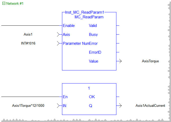
Example 3 - Reading the Current to Units of Amps
After reading the current using MC_ReadParam, this equation converts current to amps for a 12 amp peak drive:
MC_AXIS_PARAM_TORQUE_ACTUAL * Drive Continuous Current Rating / 1000