Create a Linear or Circular Coordinated Motion Application
A Coordinated Motion application can be created in one of two ways:
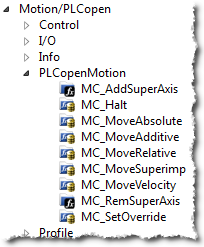
- Use a Coordinated Motion template to create a new application. Two Coordinated Motion templates are currently available.
- The first template controls two PLCopen
 A vendor -and product- independent worldwide association active in Industrial Control and aiming at standardizing PLC file formats based on XML axes in coordinated motion.
 - The second template controls two PLCopen axes in coordinated motion plus a third independent Pipe Network axis.
- The first template controls two PLCopen
- Modify an existing application to included coordinated motion functions. When modifying an existing application, axes need to be grouped to define the axes that will be active when performing coordinated motion on that group. More information about Axes Groups can be found in the section What are Axes Groups?.
-
-
Coordinated motion can only be performed with PLCopen axes. Pipe Network axes do not support this feature, although Pipe Network axes can be moved independently from coordinated motion groups. Any synchronization between coordinated motion and Pipe Network axes must be performed by the PLC
"Programmable Logic Controller"
A Programmable Logic Controller, PLC, or Programmable Controller is a digital computer used for automation of industrial processes, such as control of machinery on factory assembly lines.
Used to synchronize the flow of inputs from (physical) sensors and events with the flow of outputs to actuators and events application.
Related axes are "grouped" in an axes group. Coordinated motion is then performed on an axes group. For more information see What are Axes Groups?.
-
-
There are two vital concepts to remember when making interpolated motion.
- Interpolated motion requires creating a motion group that results in a second group coordinate system.
- Group coordinate system positions are only affected by group motion, and non-group coordinate system positions are only affected by non-group motion.
Group motion commands Non-Group motion commands 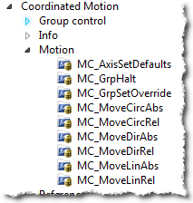
-
-
Typically axes that become part of a motion group are first homed using non –group function blocks to establish a home or starting position for the group motion.
Typically, the following set of function blocks should be called before executing coordinated motion.
-
Call MLMotionInit (BasePeriod) to initialize the motion engine. Base period is specified in microseconds.
MLMotionInit(1000.0); // 1000 µSec -> 1 mSec
-
Call MC_CreateAxesGrp (Enable, GroupName, UpdateRate, MaxNumberOfAxes, AxesGroupRef) to create a Coordinated Motion Axes Group
-
-
MC_CreateAxesGrp needs to be called between MLMotionInit() and MLMotionStart().
Inst_MC_CreateAxesGrp(TRUE, 'GROUP1', 6, 2, Group1_ref);
In the example above, the axes group name is 'GROUP1', the update rate is 1 mSec (specified by '6') and the maximum number of axes that can be added to the group is 2. The group reference variable 'Group1_ref' will be used in future coordinated motion function block calls to reference this newly created group.
-
-
Call MC_InitAxesGrp (Enable, AxesGroup, VelLimit, AccLimit, DecLimit, JerkLimit) to initialize the path limits for velocity, acceleration, deceleration, and jerk
In physics, jerk is the rate of change of acceleration; more precisely, the derivative of acceleration with respect to time.Inst_MC_InitAxesGrp(TRUE, Group1_ref, 100.0, 300.0, 300.0, 1000.0);
In the example above, the kinematic limits for axes group 'Group1_ref' will be set. The velocity limit will be set to 100.0 user units/second, acceleration and deceleration limits will be set to 300.0 user units/second2 and jerk will be set to 1000.0 user units per second3 (Jerk
In physics, jerk is the rate of change of acceleration; more precisely, the derivative of acceleration with respect to time will be supported in a future release). -
Call MC_CreatePLCAxis (AxisName, BusInterface, BusAddress, AxisNumber, AxisType, UserUnits, FeedbackUnits, Rollover, UpdateRate) to create a Coordinated Motion Axis. This function needs to be called for each Coordinated Motion Axis wanted in the application.
-
-
MC_CreatePLCAxis needs to be called between MLMotionInit() and MLMotionStart().
Inst_MC_CreateAxis(TRUE, 'CoordAxis1', 'EtherCATDriver', 1001, CoordAxis1_AxisNum, 0, 360, 1048576, 0, 6);
Inst_MC_CreateAxis(TRUE, 'CoordAxis2', 'EtherCATDriver', 1002, CoordAxis2_AxisNum, 0, 360, 1048576, 0, 6);
In the example above:
- Two axes are created and are named 'CoordAxis1' and 'CoordAxis2'.
- The bus interface for both is 'EtherCATDriver'.
- The address of the drive on the bus is 1001 and 1002.
- The axis numbers are set with variables CoordAxis1_AxisNum and CoordAxis2_AxisNum which is set to an integer value between 1 and 256. Each axis number is unique.
- The axis type for both, '0', indicates a servo axis.
- The user units are 360, which is the 'user unit' portion of the 'user unit/feedback' ratio.
- The feedback units are 1048576, which is the 'feedback' portion of the 'user unit/feedback' ratio.
- The rollover position for both, '0' indicates no rollover.
- The update rate for both, '6', indicates a 1mSec update rate.
-
-
Call MLMotionStart () to start the Motion and the motion bus driver. This also initializes the EtherCAT
***EtherCAT is an open, high-performance Ethernet-based fieldbus system. The development goal of EtherCAT was to apply Ethernet to automation applications which require short data update times (also called cycle times) with low communication jitter (for synchronization purposes) and low hardware costs network to operational mode.MLMotionStart();
-
Call MC_AddAxisToGrp (Execute, AxesGroup, Axis, IdentInGroup) for each axis to be added to the group.
Inst_MC_AddAxisToGrp(TRUE, Group1_ref, CoordAxis1_ref, 0);
Inst_MC_AddAxisToGrp(TRUE, Group1_ref, CoordAxis2_ref, 1);
In the example above, we are adding two axes, CoordAxis1 and CoordAxis2, to the group referenced by 'Group1_ref'. The axes are stored in the IdentInGroup positions 0 and 1. Note that when the group was created, it was specified that no more than 2 axes will be part of this group. Therefore, valid IdentInGroup locations are 0 and 1.
-
Call MC_Power (Enable, Axis, EnablePositive, EnableNegative, BufferMode) for each Coordinated Motion Axis to enable the drive and close the servo loop.
Inst_MC_Power1(TRUE, CoordAxis1_ref, TRUE, TRUE, 0);
Inst_MC_Power2(TRUE, CoordAxis2_ref, TRUE, TRUE, 0);
In the example above, drives CoordAxis1_ref and CoordAxis2_ref will be enabled and the position loop will be closed. Note that parameters 'TRUE, TRUE, 0' are place holders for future use and are not currently used.
-
Call MC_GrpEnable (Execute, AxesGroup) to change the state of the Coordinated Motion Axis Group from GroupDisabled to GroupStandby and allow motion to be performed on the group.
Inst_MC_GrpEnable(TRUE, Group1_ref);
In the example above, 'Group1_ref' state will be changed from GroupDisabled to GroupStandby. The group must be in GroupStandby in order to perform motion.
-
For the examples that follow, we want to set the current location of the axes in the group to 0, 0. This can be done by calling MC_GrpSetPos (Execute, AxesGroup, Position[], Relative, CoordSystem, BufferMode)
PosAbs[1]:= 0;
PosAbs[2]:= 0;
Inst_MC_GrpSetPos(TRUE, Group1_ref, PosAbs, 0, MC_COORDINATE_SYSTEM_ACS, 0);
In the example above, the axis positions of 'Group1_ref' will be set to 0, 0. 'PosAbs' specifies the position for each axis in the group. 'Relative' input, '0', uses 'PosAbs' to set the absolute position. The coordinate system is set to ACS . The buffer mode, '0', is a placeholder for future use and is not currently used.
-
-
No motion will be performed when this function block is executed.
-
-
Optional: To Add more axes to the group, modify the above code in the following way:
- In Step 2: Update the MaxNumberOfAxes input argument so that the group can handle the desired number of axes.
- In Step 4: Create the additional axes that will added to the group.
- In Step 6: Add the additional axes to the group.
- In Step 7: Power on the additional axes.
- In Step 9: You will need to increase the size of the PosAbs array so it matches the number you used in step 2, and set the position of the additional axes to zero.
After the above function calls have been made, we can start coordinated motion moves.


