Registration Position Capture Example with Pipe Network Trigger Block
A Pipe Network Trigger block can be used for registration applications to capture a pipe position based on a timestamp which is set when a drive's fast input changes state. A Trigger block is placed in the Pipe Network precisely where the pipe position needs to be captured.
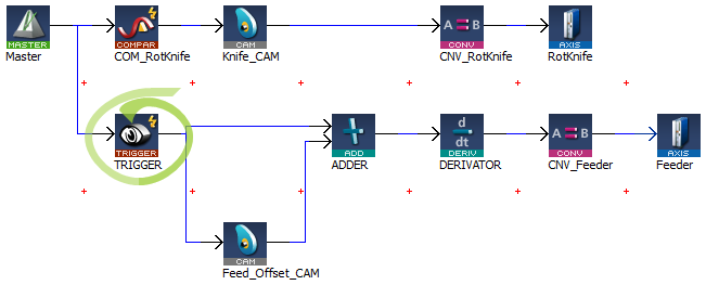
Figure 1: Example of using a Pipe Network Trigger block for position capture.
The Pipe Network motion engine captures the pipe position by using the timestamp received from the drive and interpolating two consecutive pipe position updates. The timestamp will have a delay getting into the pipe network from the drive (typically 1-2 cycles) due to sensor delay and the communication latency through the EtherCAT network (typically 1-2 cycles).
Corrected timestamp: = Fast input timestamp - DelayCompensation
To account for this delay, MLTrigWriteDelay provides delay compensation to the pipe position returned in MLTrigReadPos based on the expected delay.
The Trigger block is first configured by clicking on the block in a pipe network and setting the following parameters.
| Function | Description |
|---|---|
| INPUT_AXIS | Defines the axis whose Fast Input is used. This name is the same given to the corresponding axis block in the Pipe Network |
| INPUT_ID | Indicates which one of the two available Fast Inputs in that particular axis is used. The value can be MLFI_FIRST or MLFI_SECOND for the trigger block to be triggered on the arrival of the first or the second input respectively. Specify one of the following constants: MLFI_FIRST or MLFI_SECOND for the trigger block to be triggered on the arrival of the first or the second input respectively. |
| TRIGGER_MODE | Indicates if the trigger block responds to the rising edge or the falling edge of the Fast Input Specify one of the following constants: MLFI_RISING_EDGE or MLFI_FALLING_EDGE |
Figure 2: Configuration of the Trigger block
After configuring the Trigger block, the order of calls to its motion library functions is as follows:
- MLTrigWriteDelay(DINT,TriggerID,LREAL,delay)
- This function sets the delay compensation, typically starting with a value of 2 usec + (1 or 2) EtherCAT cycles.
- MLTrigSetEdge(PipeNetwork.TRIGGER1,MLFI_FIRST,MLFI_RISING_EDGE)
- This function reconfigures the edge of a trigger lock.
- This function only needs to be called if the desired edge is different than the edge specified in configuration of the trigger block or if the edge is different than the previous capture.
- MLAxisCfgFastIn(PipeNetwork.AXIS1, MLFI_FIRST, MLFI_RISING_EDGE)
- This function call is necessary at least one time, even if the Trigger pipe block is configured properly
- MLTrigIsTrigged(PipeNetwork.TRIGGER1)
- This function returns TRUE if the Fast Input associated to the Trigger pipe block given as argument has been triggered
- MLTrigReadPos(PipeNetwork.TRIGGER1)
- This function returns the position of the Pipe Network at the time that the Fast Input associated with the Trigger pipe block was issued
-
-
You have to correct the position by taking into account the delay due to the number of cycles needed to read the timestamp of the Fast Input. You can use MLTrigWriteDelay to address this issue.
- MLTrigReadTime(PipeNetwork.TRIGGER1)
- This function returns the time associated with the Fast Input as explained in Interpret a Timestamp.
Note that this function is of lesser importance compared to the previous one. - MLTrigClearFlag(PipeNetwork.TRIGGER1)
- This function rearms the Trigger pipe block
- MLAxisRstFastIn(PipeNetwork.AXIS1, MLFI_FIRST)
- This function rearms the Axis pipe block
After the Trigger block pipe position is determined and calculations are made in the Registration program, a corrective move is typically done using a Cam Pipe Network block for precision motion control.


