-
-
Click a Pipe Block icon to view its description.
Flow
Drive
Load


 Master
Purpose
In contrast to the independent axes approach, synchronized axes must have something to put them in synchronization.
- This is the main goal of the Master pipe block which contains a Trapezoidal Motion Profile (TMP) generator, which gives the cadence to the machine.
- It starts, stops and runs the machine at the desired speed.
The TMP Generator provides linear acceleration and deceleration, and also constant speed operation.
- These values are pure logical values, with generally no direct physical representation.
- It is a source block which frequently serves as a virtual master for a system comprised of several pipes.
- A TMP Generator may be commanded to produce a movement of specified length (distance), or to accelerate to setpoint rate and operate at that rate until commanded to operate at a different rate.
- Acceleration and deceleration rates are also specified by the application.
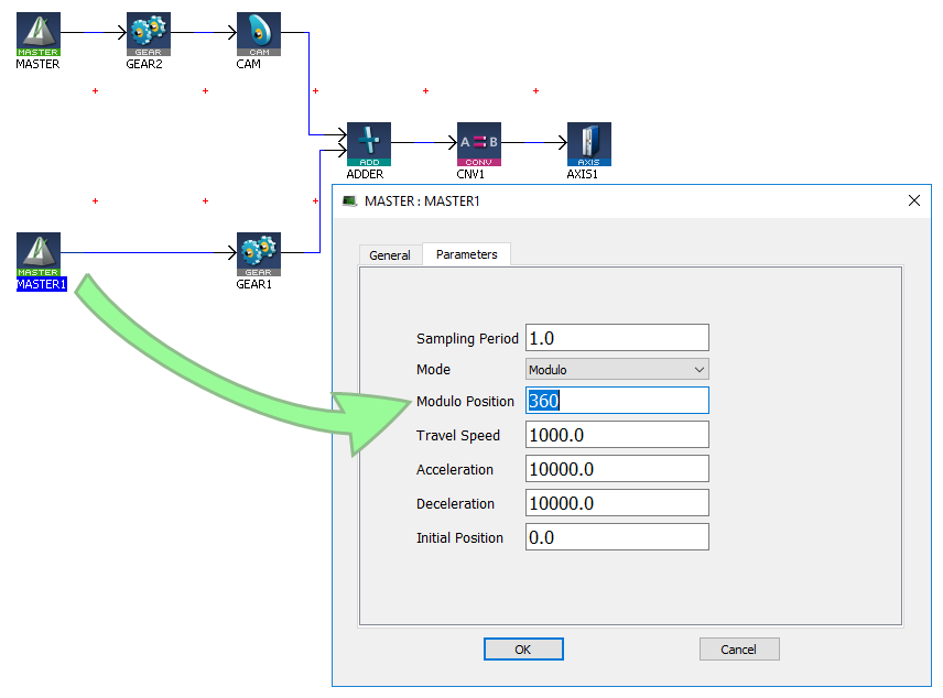
Parameters
|
Parameter |
Description |
|---|---|
|
Sampling Period |
Sampling period of the generator expressed according to the cycle. Example: 2.0 means the sampling is done once every 2 cycles. |
|
Mode |
The available modes are Modulo and No Modulo. |
|
Modulo Position |
Modulo Position for cyclic motion systems expressed in user logical units. |
|
Travel Speed |
Travel speed value expressed in user position units per second. The travel speed value is used to set the constant speed part of the trapezoidal motion profile. |
|
Acceleration |
Acceleration value expressed in user position units per second squared. The acceleration value is always used to generate the first part of the trapezoidal motion profile. |
|
Deceleration |
Deceleration value expressed in user position units per second squared. The deceleration value is always used to generate the last part of the trapezoidal motion profile. |
|
Initial Position |
Initial position value expressed in user position units. Used only at the pipe activation to initialize the position starting point. |
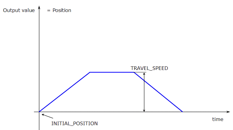
Figure 1: TMP Parameters: INITIAL_POSITION and TRAVEL_SPEED
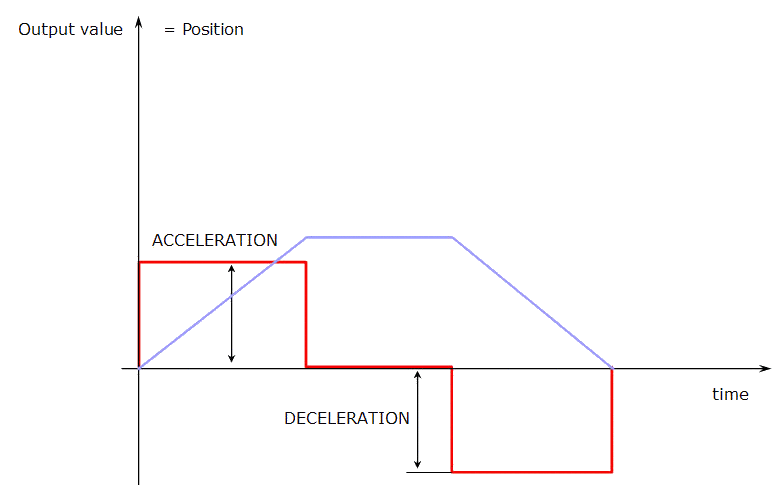
Figure 2: TMP Parameters: ACCELERATION and DECELERATION
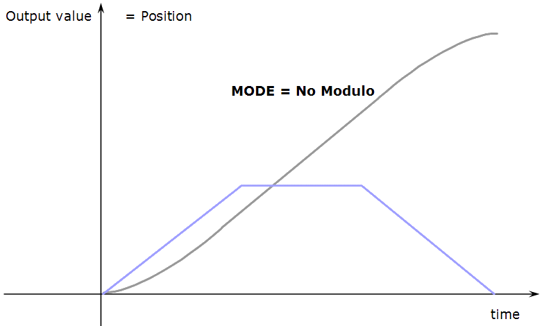
Figure 3: TMP Parameters: MODE "No Modulo"
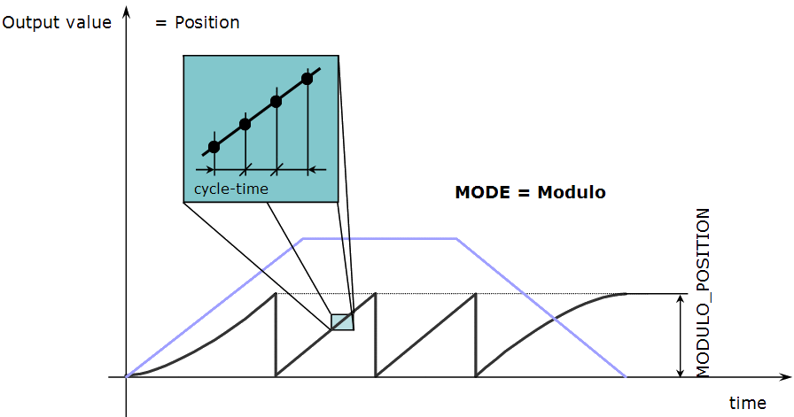
Figure 4: TMP Parameters: MODE Modulo and MODULO_POSITION
Associated Data
- OutputValue: output value of the data flows.
- IsReady: Boolean set to TRUE when the pipe block is ready.
Motion Functions
See PMP to access the motion functions associated to this pipe block.
PMP
Purpose
PMP (Parabolic Motion Profile) pipe block generates a flow of values with a second derivative (acceleration) which produces a trapezoidal trajectory.
- The PMP Generator is similar to the TMP Generator.
- It is useful in applications where jerk (third derivative of the motion) limiting is necessary.
- You can specify the maximum instantaneous rate of change of acceleration.
Uses
The PMP Generator is utilized as a virtual master to generate a simple point-to-point profile in machinery where large masses are being rotated or delicate webs (used in industry) are being processed.
It is used in any application where jerk must be limited.
The PMP Generator is capable of producing forward-backward motions with a non-stop, jerk-free transition through zero speed.
- See the image.
- This feature is frequently used for linear axes which must make a quick back-and-forth motion without any pause at one end.
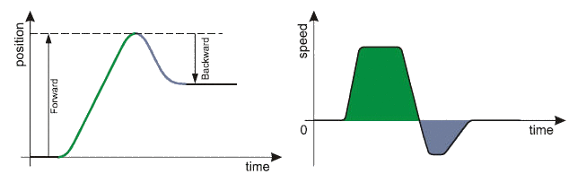
Figure 5: PMP Generator Forward and Backward Motion Profile
Parameters
|
Parameter |
Description |
|---|---|
|
Sampling Period |
Sampling period of the generator expressed in seconds. |
|
Modulo Position |
Modulo Position for cyclic motion systems expressed in user logical units. |
|
First Travel Speed Last Travel Speed |
Travel speed values expressed in user position units per second. The travel speed values are always used to set the constant speed part of the motion profile. |
|
Acceleration |
Acceleration value expressed in user position units per second squared. The acceleration value (subject to constraints imposed by the JERK parameter) is always used to generate the portions of the motion profile where velocity is changing. |
|
Jerk |
Jerk value expressed in user position units per second cubed.
|
|
Initial Position |
Initial position value expressed in user position units, used only at the pipe activation to initialize the position starting point. |
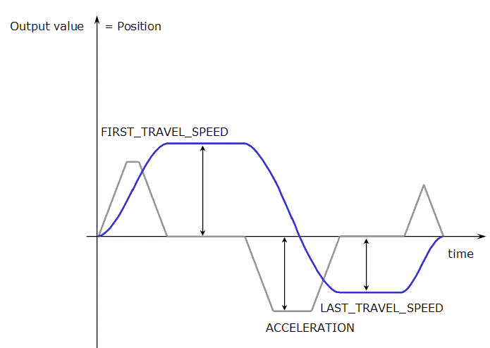
Figure 6: PMP Parameters: FIRST_TRAVEL_SPEED, LAST_TRAVEL_SPEED and ACCELERATION
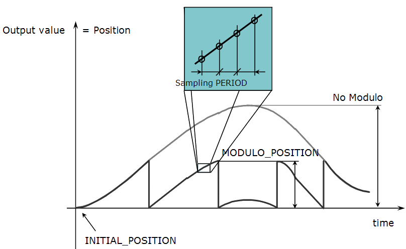
Figure 7: PMP Parameters: INITIAL_POSITION, "No Modulo" and MODULO_POSITION
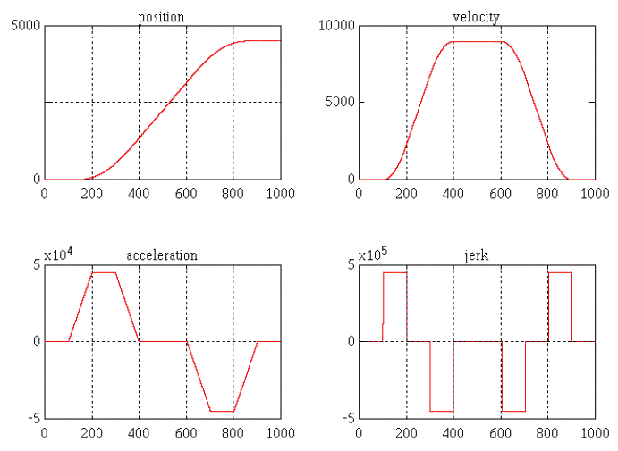
Figure 8: PMP Motion Profiles for a Relative Move
This figure shows the position, speed, acceleration and jerk profiles generated by a move of 4500 position units forward followed immediately by a backward move of 2000 position units.
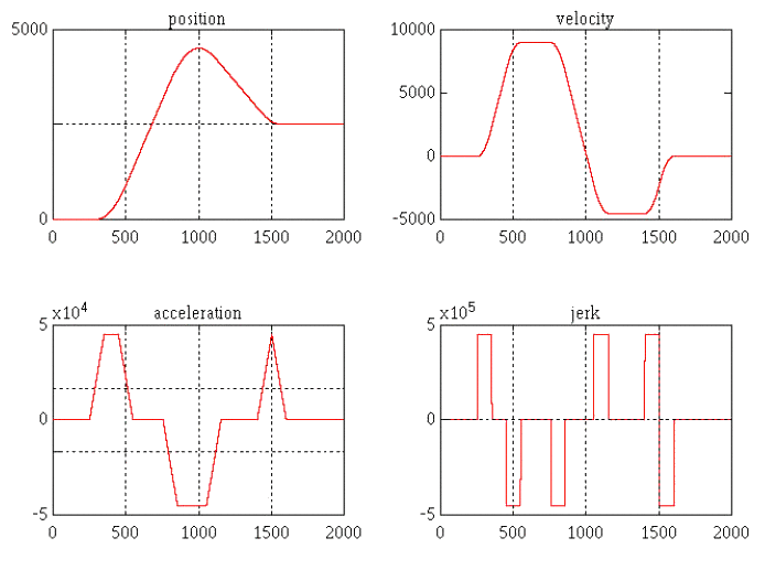
Figure 9: PMP Motion Profiles for a Forward-Backward Motion
Associated Data
- OutputValue: output value of the data flows.
- IsReady: Boolean set to TRUE when the pipe block is ready.
Motion Functions
See PMP to access the motion functions associated to this pipe block.

Sampler
Purpose
The purpose of the sampler block is to periodically sample and place into a pipe some output of a source object.
Example: The sampled output might be the POSITION or SPEED of the source object measured by a resolver, an encoder, or some other types of sensor.
The sampler implements a logical connection between an external master (source object outside the KAS system) and one or more pipes. This is for slaving the motion of the KAS system to the external master by placing the sampled values into the pipes.
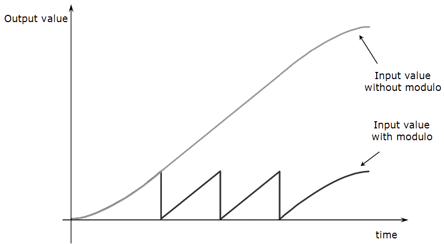
Figure 10: Sampler
Parameters
| Parameter | Description |
|---|---|
| Sampling Period |
Period of the sampler expressed in seconds
Figure 11: Sampler Period |
| Mode |
The available modes are Position and Speed
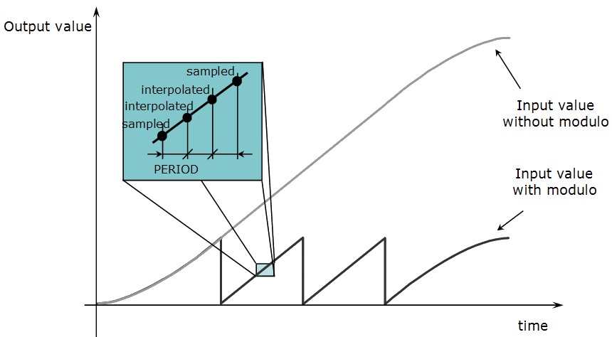
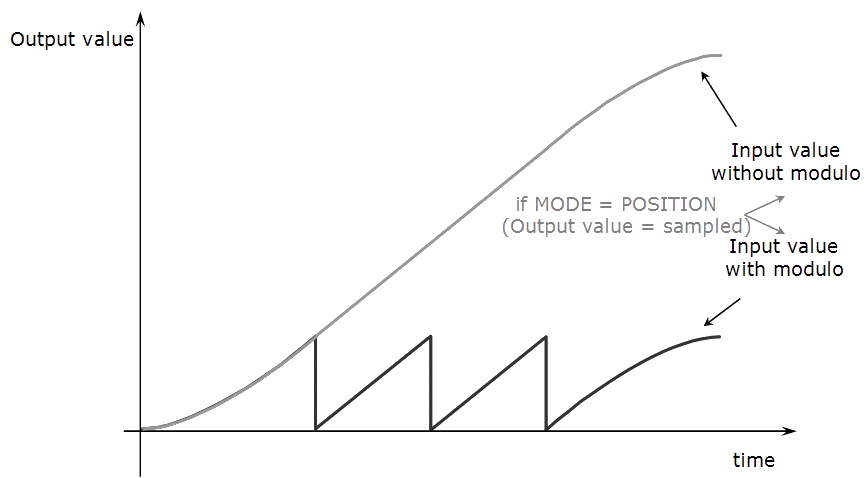
Figure 12: Sampler Mode Position
Figure 13: Sampler Mode Speed |
This image illustrates the concept.
The Sampler feeds motion trajectory data derived from an encoder (or resolver) coupled to the remote machine into the Pipe Network.
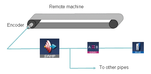
Figure 14: Sampler Pipe Block Used to Track an External Master
Associated Data
- OutputValue: output value of the data flows.
- IsReady: Boolean set to TRUE when the pipe block is ready.
Motion Functions
See PMP to access the motion functions associated to this pipe block.
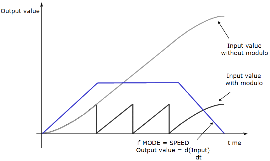
Derivator
Purpose
The Derivator is a general pipe block whose purpose is to calculate the first derivative of its input values with respect to time.
- It is usually used to change incoming position into velocity.
- It often works together with the GEAR block as gearing in velocity to avoid jumps when suddenly changing the position.
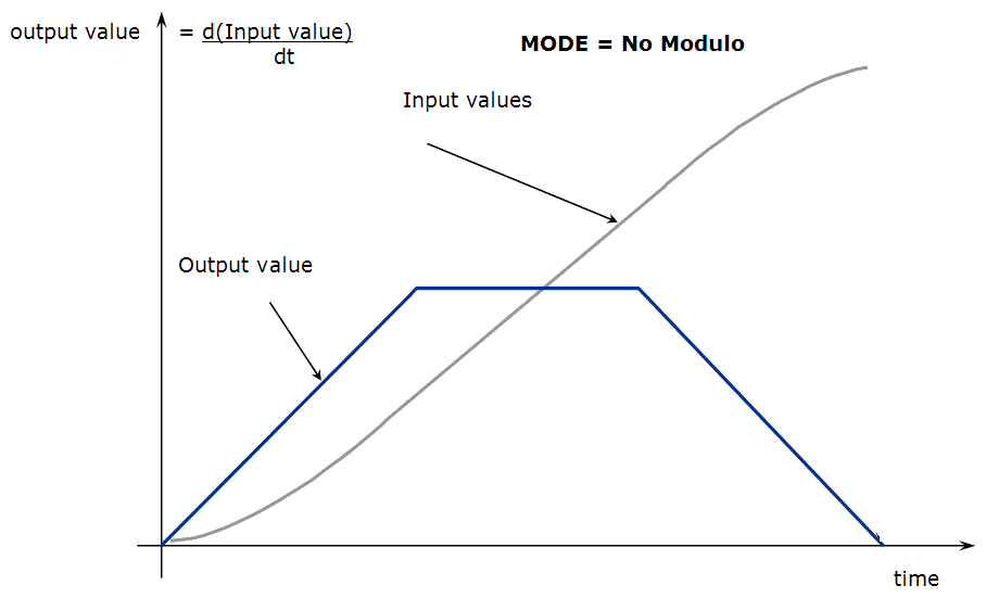
Figure 15: Derivator - "No Modulo" Mode
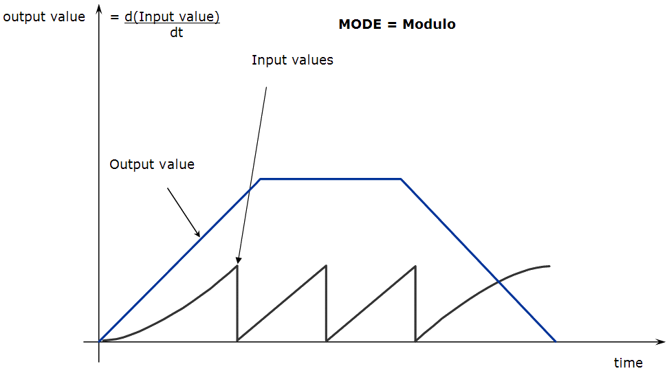
Figure 16: Derivator - Modulo Mode
Parameters
| Parameter | Description |
|---|---|
| Input Modulo Position |
Value of the period of a cyclic system expressed in user units. Example: If the input value increases each millisecond by one (degree) then the output value is a thousand (degrees per second). Imagine the input value skips suddenly from 359 to 0:
|
Initial Behavior
The first calculation of a Derivator pipe block just after the pipe installation indicates zero regardless of the initial input value.
Associated Data
- OutputValue: output value of the data flows.
- IsReady: Boolean set to TRUE when the pipe block is ready.
Motion Functions
To access the motion functions associated to this pipe block, see click here....
Integrator
Purpose
Integrates the input data flow.
Usually used to change velocity to position and the output is the starting point from where the integration starts.
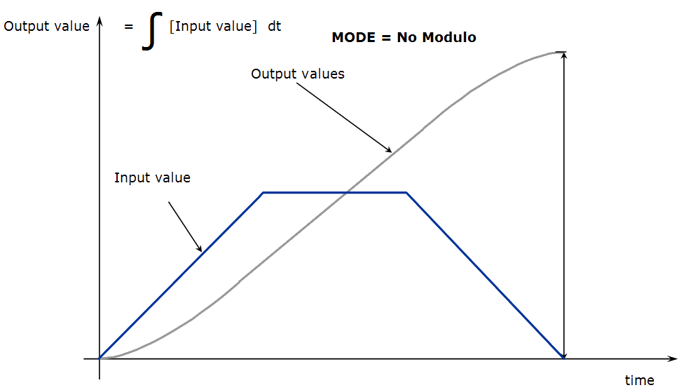
Figure 17: Integrator - "No Modulo" Mode
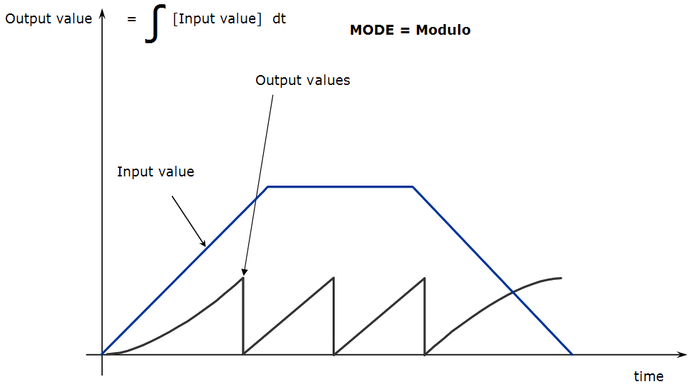
Figure 18: Integrator - Modulo Mode
Parameters
| Parameter | Description |
|---|---|
| Mode | The available modes are Modulo and "No Modulo" |
| Output Modulo Position |
When mode is set to Modulo, integrate the input values with respect to time. "OUTPUT_MODULO_POSITION" is defined to correctly manage the periodicity (modulo) of the output values. |
Associated Data
- OutputValue: output value of the data flows.
- IsReady: Boolean set to TRUE when the pipe block is ready.
Motion Functions
To access the motion functions associated to this pipe block, see click here....
Adder
Purpose
Adds two data flows (the output is the algebraic sum of the two inputs).
Before being added, input values may be amplified and shifted (multiplication factor and offset are individually defined for each input).
Parameters
|
Parameter |
Description |
|---|---|
|
Ratio |
Multipliers for the input data flows. |
|
Offset |
Offset values for the input data flows. |
Output = (Ratio_1 * Input_1 + Offset_1) + (Ratio_2 * Input_2 + Offset_2)
Rules
Rule 1 and Rule 2 apply to the Adder pipe block.
Rule 1
The pipe blocks connected to the Adder inputs (e.g., a Cam and a Gear) must have the same output modulo positions.
Rule 2
The modulo position of the pipe blocks connected to the Adder inputs must have the same value (or a multiple) as the modulo position of the pipe block connected to the output of the Adder.
Associated Data
- OutputValue: output value of the data flows.
- Entry1: input value 1.
- Entry2: input value 2.
Motion Functions
To access the motion functions associated to this pipe block, see Adder.
Synchronizer
Purpose
The Synchronizer provides the capability to de-synchronize and re-synchronize an axis to an internal or external master like a mechanical clutch / brake.
- It is used where a slave axis must be stopped and, when restarted, achieve perfect, jerk-free re-synchronization with the master.
- The ramping distance (increment of slave axis motion within which ramp up or ramp down occurs) and the slave axis resting position are adjustable.
Parameters
Such a pipe block can be used, for instance, when an item is missing on a conveyor.
Figure below illustrates the application of a Synchronizer which enables a slave axis to be stopped, started and re-synchronized to an external master.
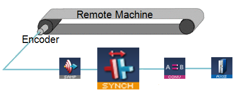
Figure 19: Synchronizer Pipe Block to Start, Stop and Re-synchronize a Slave Axis
Associated Data
- OutputValue: output value of the data flows.
- IsReady: Boolean set to TRUE when the pipe block is ready.
Motion Functions
To access the motion functions associated to this pipe block, see click here....
Delay
Purpose
Delay the data flow a number of cycles.
Parameters
| Parameter | Description |
|---|---|
| Cycle Delay | Number of cycles for postponement |
Associated Data
- OutputValue: output value of the data flows.
- IsReady: Boolean set to TRUE when the pipe block is ready.
Motion Functions
See click here... to access the motion functions associated to this pipe block.
Comparator
Purpose
A Comparator monitors the flow of pipe data and causes a specified action when the flow of values at its input crosses a specified reference value.
- A Comparator is used for synchronizing the operation of an actuator to the position of a product or axis in a machine cycle.
- The Comparator block does not modify flow values and has no effect on the axis and its periodicity.
Parameters
The necessity to use the through zero reference mode is illustrated in this example.
Assume:
- The system is a periodic system with a Modulo Position of 500.
- The system is running in the positive direction (pipe flow values increase).
- Imagine that the position of the system is
now 400 and you want to wait for the system to reach 326 again.
- If you ask for the Comparator to detect the 326 reference in normal mode, it immediately sets the ready flag at true (400 > 326) but this is not what you want.
- If you ask for the Comparator to detect the 326 value in through zero reference mode, it waits for the system to cross one zero reference (cross the position value = 0) and then triggers the application when the correct condition is fulfilled.
There is a big difference in response time when using a Boolean equation to compare a value with a reference, versus using a Comparator pipe block do to the same processing.
- With the Boolean equation, KAS periodically performs the comparison, ignoring any dynamics taking place between successive comparisons, which could result in delays in triggering sequences, and possible loss of information when the pipe-flow value crosses the reference momentarily between comparisons.
- With a Comparator, the value of the ready flag is intrinsically updated each time a new pipe-flow value is computed. Therefore, it is impossible to lose any transitions.
This image illustrates an example application of the Comparator.
- An output valve controlled by a Comparator is added to the filling mechanism from the example in the Cam pipe block.
- When cam position crosses the value "Trigger 1", the Comparator initiates the "Open Routine" which, in turn, opens the output valve.
- Next, the Comparator is set
to the value "Trigger 2".
- When the cam position crosses the "Trigger 2" value, the Comparator initiates the "Close Routine" and the valve is closed.
- The Comparator is again set to the value of "Trigger 1" and the cycle restarts.
- A user output resident in the Drive operates the valve.
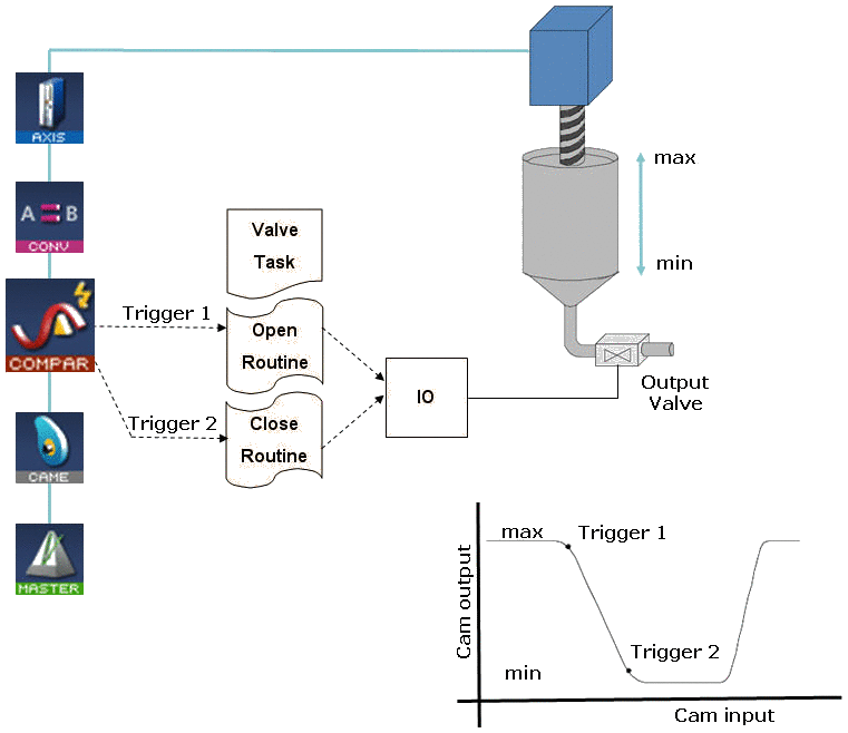
Figure 20: Comparator Used to Control a Valve on a Filler Mechanism
Associated Data
- OutputValue: output value of the data flows.
- IsReady: Boolean set to TRUE when the pipe block is ready.
Trigger
Purpose
Computes the local pipe value from the timestamp of a Fast Input time event.
- Pipe input values are passed through to the block output with no influence on the flow of pipe values.
- Typical application is for PLCopen Registration.
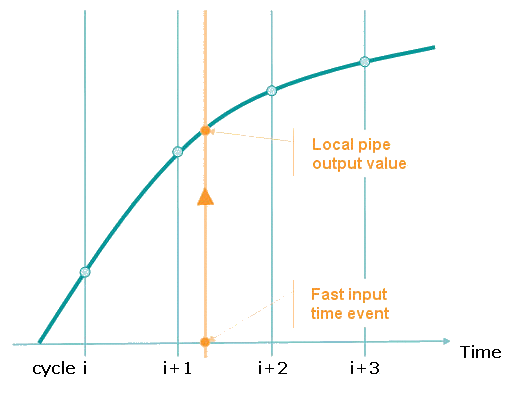
Figure 21: Trigger Extrapolates Output Value Based on Fast Input Timestamp
-
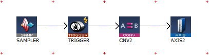
- There are network and mechanical delays in systems that make capturing a correct pipe position difficult. To remove the delays, use a sampler block to capture the actual position of an axis. This image shows how this works:
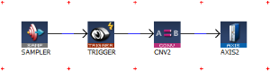
This sampler block is configured to capture the actual position of axis 1. The conversion and axis blocks are only needed to terminate the pipe. MLTrigWriteDelay may still be needed to compensate for sensor delay.
If you need to calculate the master pipe value corresponding to the captured axis position, add the difference between the axis command position and the master pipe value.
Parameters
| Parameter | Description |
|---|---|
| Input Axis | Name of the axis where the drive has a Fast Input connection. |
| Input ID | Identifier of the input object. |
| Trigger Mode | Mode can be either RISING or FALLING EDGE |
Associated Data
- OutputValue: output value of the data flows.
- TRIG_POS: interpolated position calculated when the time event was triggered (reserved for debugging purposes).
- TRIG_TIME: time when the event was triggered (reserved for debugging purposes).
- DELTA_TRIG_TIME: reserved for debugging purposes.
Motion Functions
To access the motion functions associated to this pipe block, see click here....
See Fast Inputs with Pipe Network Motion for more details.
Gear
Purpose
The purpose of the Gear block is to amplify / attenuate (with a ratio) and shift (with an offset) the flow of values.
- A Gear may have a ratio and offset less or greater than one, or even zero.
- Ratio and offset may be changed dynamically during application execution.
- A slope may be specified to limit the rate at which step changes in ratio and offset are implemented.
Parameters
| Parameter | Description |
| Ratio | Ratio coefficient |
| Offset | The input offset value. |
| Ratio and Offset Slope |
Sets the maximum rate of change at the pipe block output resulting from changes in RATIO or OFFSET parameters.
|
| Modulo |
When set to TRUE, adapts the output values according to the periodicity (modulo). |
Output = Ratio * Input + Offset
Associated Data
- OutputValue: output value of the data flows.
- IsReady: Boolean set to TRUE when the pipe block is ready.
- INPOS: reserved for debugging purposes.
Motion Functions
To access the motion functions associated to this pipe block, see click here....
Cam
Purpose
The Cam block is used to generate motion profiles of any shape. The profile generally represents the position transformation.
-
-
Jerk may ultimately cause a jerk in motor motion when a cam block is applied to the upstream pipe network positions.
To avoid jerk in the pipe network, the potential position offset between the cam's first point and the input to the cam block must be taken care of in the application program by setting a cam offset or another method.
Declarations
Separating the declaration of the Cam and profile parameters for the Cam pipe block provides the capability to declare and prepare several different cam profiles and then apply one of these dynamically to the Cam pipe block.
Profile switching may be done on the fly, without losing the synchronization and with no dead time.
In addition, the periodicity of the cam output values can be specified when used with a periodic system.
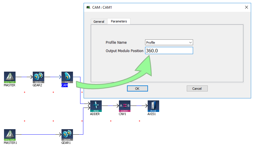
Parameters
| Parameter | Description |
|---|---|
| Profile Name |
Name of the current profile assigned to the cam. It must be a declared profile object. |
| Output Modulo Position | Value of the period of the cam output values expressed in user units, for a cyclic system. |
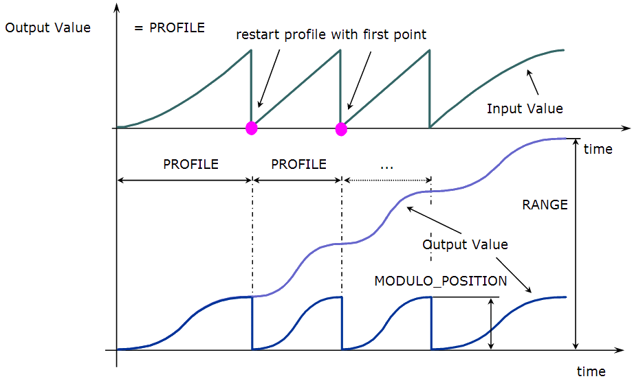
Figure 22: Cam Parameters
When a MODULO_POSITION is defined, the output value is reset each time it reaches the MODULO_POSITION.
Shape Specification
The shape of the cam profile must be processed by the Cam Profile Editor utility before it is usable by the Pipe Network Editor.
- The shape of the profile is represented by a table of numerical values.
- These values can be generated using software tools such as spreadsheets or specialized cam software.
- The KAS Cam Editor software tool provides the capability to visualize, analyze, edit and smooth profiles.
- Cam blocks have gain as well as offset adjustment capabilities.
- Axis position is usually the profile variable; however, velocity or torque profiles may also be generated.
The mathematical relationship of the cam output as a function of the input and the cam parameters is:
If Oin ≤ Xi ≤ Oin + Ain then Yi = Oout + (fct((Xi - Oin)/Ain) * Aout)
Within the stated limits, these functions apply:
If  Xi < Oin then Yi = Oout + (fct(0.0) * Aout)

If  Xi > Oin + Ain then Yi = Oout + (fct(1.0) * Aout)
With:
| Parameter | Definition |
|---|---|
| Xi | Input value |
| Oi | Input offset |
| Ain | Input amplitude |
| fct | the function defining the shape |
| Yi | Output value |
| Oout | Output offset |
| Aout | Output amplitude |
This image illustrates the use of the Cam blocks in a three-axes container filler mechanism.
- The cam profile for:
- Axis 1 controls the volume of liquid dispensed and the fill rate.
- Axis 2 raises and lowers the container.
- Axis 3 indexes containers under the filling mechanism.
- All three axes track the main machine motion profile produced by a TMP Generator.
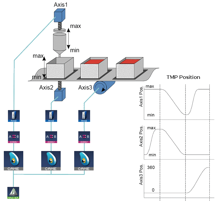
Figure 23: Cam Blocks Control Operation of a Three Axis Filling Mechanism
Associated Data
- OutputValue: output value of the data flows.
- IsReady: Boolean set to TRUE when the pipe block is ready.
Motion Functions
To access the motion functions associated to this pipe block, see click here....
Phaser
Purpose
A Phaser produces a flow of output values which are offset (phase shifted) a specified amount from its input. A typical application of a Phaser is to provide independent phase adjustment capability on an axis.
The Phaser has some similarities with the Gear pipe block, however its intended use is quite different.
- The typical application for a Phaser pipe block is to drive a periodic system: a machine where the axes are globally increasing (or decreasing) their position.
- The Gear pipe block, with OFFSET and RATIO parameters, is intended for bounded applications (applications where the integral of speed on a
complete cycle is zero).
- Using the wrong one at the wrong place will cause unnecessary complications.
- In addition, you must always consider the position as the input value (and not the speed).
Parameters
|
Parameter |
Description |
|---|---|
|
Output Modulo Position |
Defined to correctly manage the periodicity (modulo) of the output values. Expressed in User units. |
|
Phase |
Magnitude of the number added to the input value.
|
|
Phase Slope Type |
Choose between these modes to define the slope:
|
|
Phase Slope |
Rate at which phase changes are implemented, expressed in user logical units per second. A slow rate parameter is provided to limit the implementation of step changes of phase. |
|
Standby Value |
Value assumed by the phaser output when the phaser is in "stopped" condition. Expressed in user logical units. |
Associated Data
- OutputValue: output value of the data flows.
- IsReady: Boolean set to TRUE when the pipe block is ready.
Motion Functions
To access the motion functions associated to this pipe block, see click here....
Convertor
Purpose
The convertor block is necessary to define the connection between a pipe and a destination object.
- Depending on convertor mode, the incoming numerical values are converted to POSITION or SPEED setpoints with no periodicity.
- This conversion has no effect on the axis units and their periodicity.
- This block must be present at the end of a pipe, typically right before an axis block.
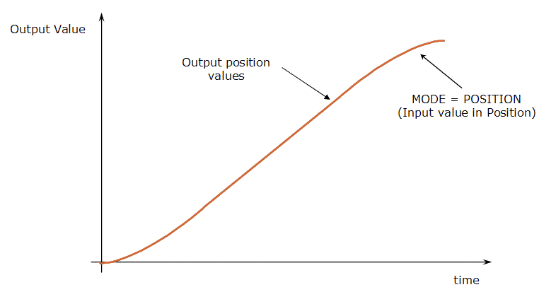
Figure 24: Convertor - Position Mode "No Modulo"
The Output position values are identical to input values when inputs in position mode (by range).
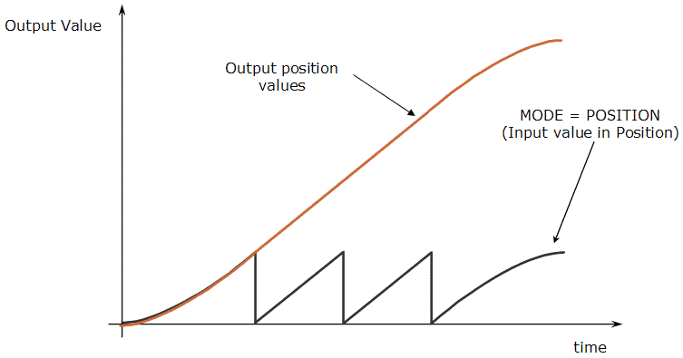
Figure 25: Convertor - Position Mode (Modulo)
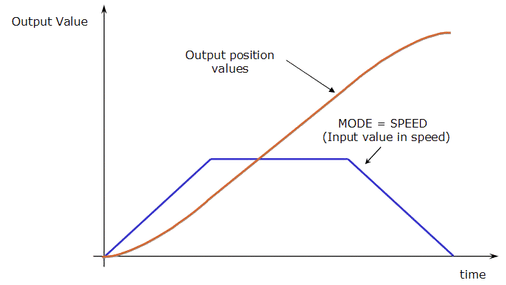
Figure 26: Convertor - Speed Mode
Parameters
| Parameter | Description |
|---|---|
| Mode |
The available modes are:
|
Associated Data
- OutputValue: output value of the data flows.
- IslinkedToAxis: Boolean set to TRUE when the Convertor pipe block is linked to an axis block.
Motion Functions
To access the motion functions associated to this pipe block, see click here....
Axis
Purpose
- Models the link from the Pipe Network to a physical axis.
- Gives access (through the fieldbus) to remote drive's functions and parameters.
- Automatically updates the image of the remote drive's status and error information.
Parameters
| Parameter | Description |
|---|---|
| Position Unit |
This field sets the units (see UNIT Parameters ) used by the drive axis. When the axis is defined as an AKD2G, the units and value are synchronized with the drive.
|
| User Units Per Revolution |
To divide the current axis into graduations adapted to your project, you must define the unit that is equivalent to one revolution of the physical motor (e.g., 3600 means that you define the user unit to be tenth of a degree). You can rely on expressions to define values. Gear factor 1:3 and 1000.0 User Units per one gear shaft revolution // user units per revolution calculation example #define DEF_BandGear 3.0 // gearbox ratio #define DEF_BandUnit 1000.0 // user units for 1 mechanical turn #set DEF_BandUUperRev DEF_BandUnit/DEF_BandGear
Figure 27: Define Value with Expressions For more details on Definitions, see Use the Defines List. |
| Unit Label |
Specify the type of units being used. This is used for display purposes. |
| Travel Speed |
Travel speed value expressed in user length units per second. The travel speed value is used to set the constant speed part of the trapezoidal motion profile. |
| Acceleration |
Acceleration value expressed in user length units per second squared. The acceleration value is always used to generate the first part of the trapezoidal motion profile. |
| Deceleration |
Deceleration value expressed in user length units per second squared. The deceleration value is always used to generate the last part of the trapezoidal motion profile. |
| Mode |
The available modes are Modulo and "No Modulo". Depending on the type of the moving object the axis acts on, you can define the MODULO_POSITION parameter or not. Moving objects, performing a never ending cyclical motion are called periodic (e.g., printing cylinder, cutting wheel). In this example, if a user unit = 0.1 mm has been chosen, a Modulo Position = 2000 Units could be selected for this transportation system.
Figure 28: Mode Modulo No Modulo Objects always moving within a certain position range (forward/backwards) can be called linear or range axes (e.g., lift axis, moving tables). In this example, if a user unit = 0.1 mm has been chosen, a position range = 0 to 10'000 Units could be selected for this moving table.
Figure 29: Mode "No Modulo"
|
| Rollover Position | Modulo Position for cyclic motion systems expressed in user logical units. |
| Motion Bus |
Select in the drop-down menu the type of motion bus associated to the axis. This is only available when using an imported ENI file. |
| Address |
Specify the address number depending on the motion bus. This is only available when using an imported ENI file. |
| Drive Axis Number |
This is only available when using an imported ENI file. |
| Drive Units per Revolution |
Number of units associated to the Drive for one revolution of the physical motor. This is only available when using an imported ENI file. |
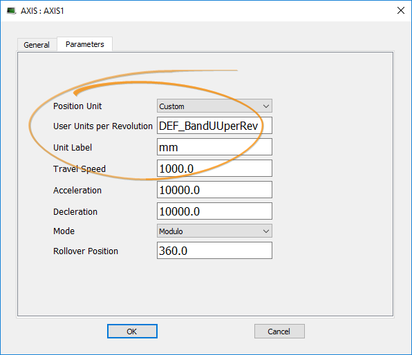
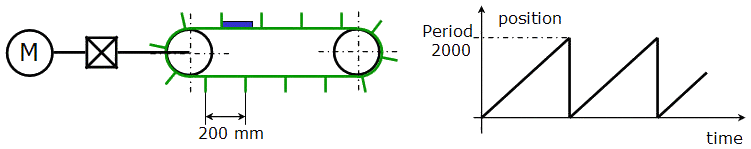
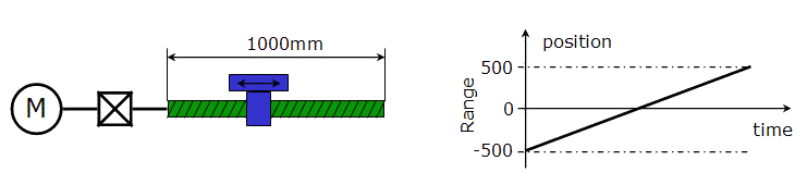
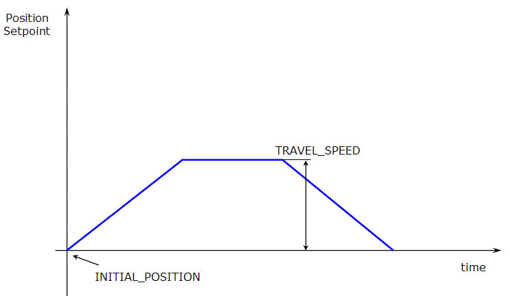
Figure 30: Axis Parameters: INITIAL_POSITION and TRAVEL_SPEED
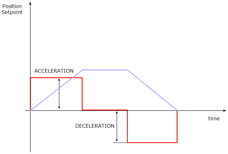
Figure 31: Axis Parameters: ACCELERATION and DECELERATION
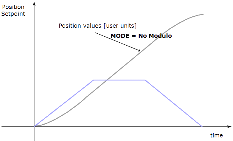
Figure 32: Axis Parameters: MODE "No Modulo"
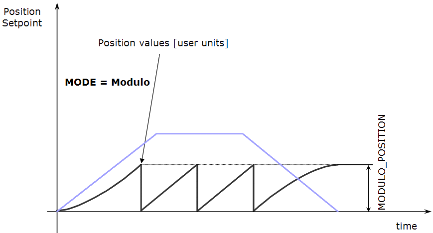
Figure 33: Axis Parameters: MODE Modulo and MODULO_POSITION
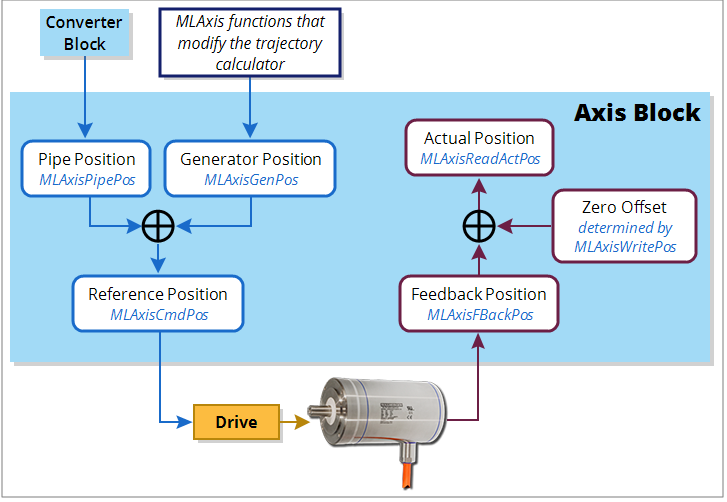
Associated Data on Positions
This data are illustrated here:
-
-
All positions are in user units with modulo applied if active, unless specified.
| Position / Offset | Description |
|---|---|
|
This is the actual position of the underlying axis as reported by the drive.
ActualPos := FeedbackPos + ZeroOffset |
|
|
This is the current position the drive reports for an axis, scaled to user units. It does not take into account the value of the Zero Offset or axis modulo. |
|
|
This is the summation of all previous commands (i.e., calls to functions which perform motion) to the Axis internal motion generator. See either such as MLAxisAbs, MLAxisMoveVel, or MLAxisRel.
|
|
|
This is the output of the convertor block is written into the Pipe Position value whenever the Convertor block is connected to the axis and the pipe is active. See Convertor. |
|
|
This is the commanded axis position sent to the drive. It is the summation of Pipe Position and Generator Position. ReferencePosition = Pipe Position + Generator Position |
|
|
This adjusts the coordinate system so the Actual Position reports correct values after homing or using MLAxisWritePos. |
Motion Functions
To access the motion functions associated to this pipe block, see click here....


