|
Name |
Description |
|
Initializes a CAM Pipe Block for use in a PLC Program. |
|
|
Switches the CAM Profile in a selected CAM object. |
|
|
Returns the Input Offset value of a selected CAM Profile. |
|
|
Returns the Input Ratio value of a selected CAM Profile. |
|
|
Returns the Output Offset value of a selected CAM Profile. |
|
|
Returns the Output Ratio value of a selected CAM Profile. |
|
|
Sets the Input Offset value of a selected CAM Profile. |
|
|
Sets the Input Ratio value of a selected CAM Profile. |
|
|
Sets the Output Offset value of a selected CAM Profile. |
|
|
Sets the Output Ratio value of a selected CAM Profile. |
|
|
Creates a CAM Profile from application data that can be executed by a CAM block in Pipe Network or PLCopen. |
|
|
Creates a new CAM Profile Object for use in a PLC Program or Pipe Network CAM block. |
|
|
Initializes a previously created CAM Profile object for use in a PLC Program or Pipe Network CAM block. |
|
|
Removes a Profile so the ProfileID can be used by a different or new Profile. |
Purpose
- The Cam block is used to generate motion profiles of any shape.
- The profile generally represents the position transformation.
-
-
Jerk may ultimately cause a jerk in motor motion when a cam block is applied to the upstream pipe network positions.
To avoid jerk in the pipe network, the potential position offset between the cam's first point and the input to the cam block must be taken care of in the application program by setting a cam offset or another method.
Declarations
- Separating the declaration of the CAM and profile parameters for the CAM pipe block provides the capability to declare and prepare several different cam profiles and then apply one of these dynamically to the CAM pipe block.
- Profile switching may be done on the fly, without losing the synchronization and with no dead time.
- The periodicity of the cam output values can be specified when used with a periodic system.
Parameters
|
Parameter |
Description |
|---|---|
|
ProfileName |
|
|
ModuloPosition |
|
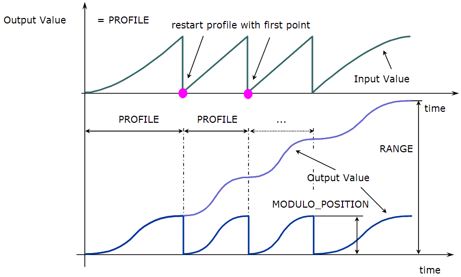
Figure 1: Cam Parameters
When a MODULO_POSITION is defined, the output value is reset each time it reaches the MODULO_POSITION.
Shape Specification
The shape of the cam profile must be processed by the Cam Profile Editor utility before it is usable by the Pipe Network Editor.
- The shape of the profile is represented by a table of numerical values.
- These values can be generated using software tools such as spreadsheets or specialized cam software.
- The KAS Cam Editor software tool provides the capability to visualize, analyze, edit and smooth profiles.
- Cam blocks have gain as well as offset adjustment capabilities.
- Axis position is usually the profile variable; however, velocity or torque profiles may also be generated.
The mathematical relationship of the cam output as a function of the input and the cam parameters is:
If Oin ≤ Xi ≤ Oin + Ain then Yi = Oout + (fct((Xi - Oin)/Ain) * Aout)
Within the stated limits, these functions apply:
If Xi < Oin then Yi = Oout + (fct(0.0) * Aout)

If Xi > Oin + Ain then Yi = Oout + (fct(1.0) * Aout)
With:
|
Parameter |
Definition |
|---|---|
|
Xi |
Input value. |
|
Oi |
Input offset. |
|
Ain |
Input amplitude. |
|
fct |
the function defining the shape. |
|
Yi |
Output value. |
|
Oout |
Output offset. |
|
Aout |
Output amplitude. |
This image illustrates the use of the Cam blocks in a three-axes container filler mechanism.
- The cam profile for:
- Axis 1 controls the volume of liquid dispensed and the fill rate.
- Axis 2 raises and lowers the container.
- Axis 3 indexes containers under the filling mechanism.
- All three axes track the main machine motion profile produced by a TMP Generator. (Figure 2)
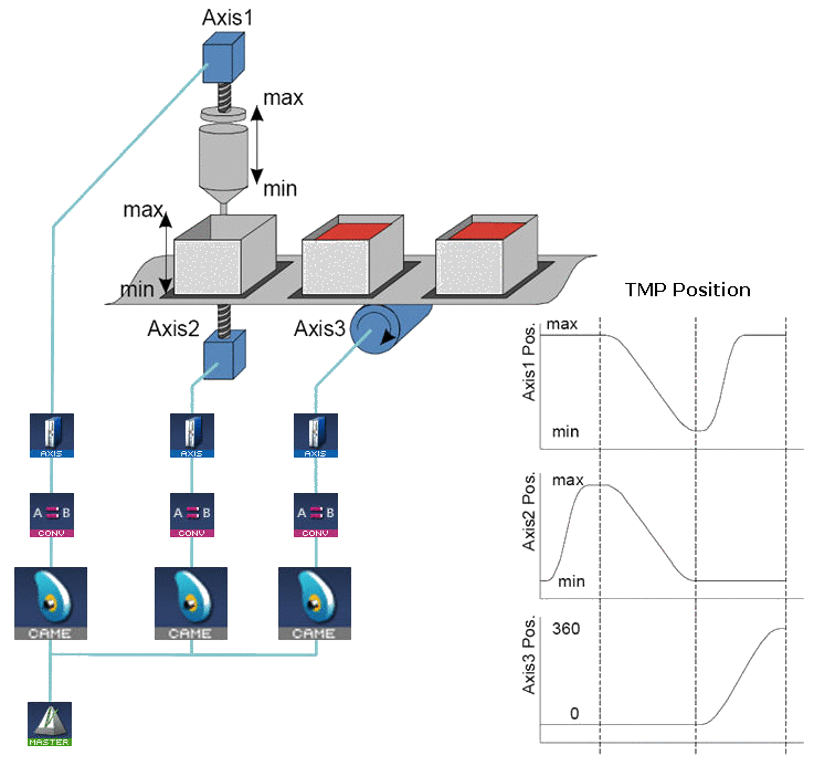
Figure 2: Example: Cam Blocks Control Operation of a Three Axis Filling Mechanism
Associated Data
- OutputValue: Output value of the data flows.
- IsReady: Boolean set to TRUE when the pipe block is ready.


