AKT2G-SM-L50-000
Stepper motor![]() An actuator focused to a movement, converting electrical energy in a force or torque. terminal, 50 V DC, 5 A, vector control
An actuator focused to a movement, converting electrical energy in a force or torque. terminal, 50 V DC, 5 A, vector control
The AKT2G-SM-L50 EtherCAT![]() Ethernet ofr Control Automation Technology.
EtherCAT® is an open, high-performance Ethernet-based fieldbus system.
The development goal of EtherCAT is to apply Ethernet to automation applications which require short data update times (also called cycle times) with low communication jitter (for synchronization purposes) and low hardware costs. Terminal is intended for stepper motors with medium performance range. The PWM output stages cover a wide range of voltages and currents. Together with two inputs for limit switches
Ethernet ofr Control Automation Technology.
EtherCAT® is an open, high-performance Ethernet-based fieldbus system.
The development goal of EtherCAT is to apply Ethernet to automation applications which require short data update times (also called cycle times) with low communication jitter (for synchronization purposes) and low hardware costs. Terminal is intended for stepper motors with medium performance range. The PWM output stages cover a wide range of voltages and currents. Together with two inputs for limit switches![]() Switch limiting the traverse path of the machine.
Implemented as n.c. (break) contact.
A sensor, typically Hall-effect, optical, eddy current, or mechanical, which is used to sense the end of travel of a linear motion assembly.
In addition to preventing over travel, it is frequently used to establish a precision reference., they are located in the EtherCAT Terminal.
Switch limiting the traverse path of the machine.
Implemented as n.c. (break) contact.
A sensor, typically Hall-effect, optical, eddy current, or mechanical, which is used to sense the end of travel of a linear motion assembly.
In addition to preventing over travel, it is frequently used to establish a precision reference., they are located in the EtherCAT Terminal.
The SM-L50 can be adjusted to the motor and the application by changing just a few parameters. 64-fold micro-stepping ensures particularly quiet and precise motor operation. Together with a stepper motor and an encoder![]() Generates an output signal directly proportional to the movement of the motor shaft.
This signal is fed into the control circuitry to control the shaft position and speed.
The most common types are: Incremental/Serial encoders, Hall effect sensors, Resolvers, Tachometer Generators
See: Optical encoders., the SM-L50 represents an inexpensive small servo axis.
Generates an output signal directly proportional to the movement of the motor shaft.
This signal is fed into the control circuitry to control the shaft position and speed.
The most common types are: Incremental/Serial encoders, Hall effect sensors, Resolvers, Tachometer Generators
See: Optical encoders., the SM-L50 represents an inexpensive small servo axis.
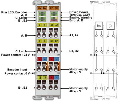
The LEDs indicate status, warning and error messages as well as possibly active limitations.
Quick Links
- About Stepper Motors
- Standard Mode
- AKT2G-SM-Lx Object Description
- AKT2G-SM-Lxx PDO Assignment
- AKT2G-SM-Lxx Diagnostic Messages
- Mounting and Wiring of I/O Terminals
- AKT2G-SM-L50 LEDs and Connections
- AKT2G-SM-L50 General Connection Examples
Technical Data
| Technical Data | AKT2G-SM-L50 |
|---|---|
| Number of outputs | 1 stepper motor, 2 phases |
| Number of digital inputs | 2 limit position |
| Number of digital outputs | 1 configurable for brake (0.5 A) |
| Supply voltage | 8 … 50 V DC |
| Motor Current/Phase (RMS) values without fan cartridge ZB8610 | 3.53 A |
| Motor Current/Phase (RMS) values with fan cartridge ZB8610 | 4.59 A |
| Maximum output current without fan cartridge AKT2G-AC-FAN-001 | 5 A (overload- and short-circuit-proof) |
| Maximum output current with fan cartridge AKT2G-AC-FAN-001 | 6.5 A (overload- and short-circuit-proof) |
| Operating modes |
|
| Maximum step frequency | 1000, 2000, 4000, 8000 or 16000 full steps/s (configurable) |
| Step pattern | up to 64-fold micro stepping (automatic switching, speed-dependent) |
| Current controller |
approx. 30 kHz |
| Encoder pulse |
maximum 400,000 increments per second (4-fold evaluation) |
| Input signal voltage "0" | -3 V … 2 V |
| Input signal voltage "1" | 3.7 V … 28 V |
| Input Current | typ. 5 mA |
| Diagnostics LED | Warning strand A and B, error strand A and B, power, enable |
| Resolution |
approx. 5,000 positions in typical applications (per revolution) |
| Power Supply | via the E-bus, encoder/driver |
| Current consumption from the E-bus | typ. 140 mA |
| Electrical isolation | 500 V (E-bus/signal voltage) |
| Support NoCoEStorage | yes |
| Configuration | no address setting required |
| Weight | approx. 105 g |
| Permissible ambient temperature range during operation | 0°C ... +55 °C |
| Permissible ambient temperature range during storage | -25°C ... + 85 °C |
| Permissible relative humidity | 95%, no condensation |
| Dimensions (W x H x D) | approx. 27 mm x 100 mm x 70 mm (connected width: 24 mm) |
| Installation | on 35 mm mounting rail according to EN 60715 |
| Vibration / shock resistance | conforms to EN 60068-2-6/EN 60068-2-27 |
| EMC immunity/emission | according to EN 61000-6-2 / EN 61000-6-4 according to IEC |
| EMC category | Category C3 - standard Category C2, C1 - auxiliary filter required |
| Protection class | IP 20 |
| Installation position |
|
| Approval | CE cULus |


