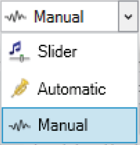
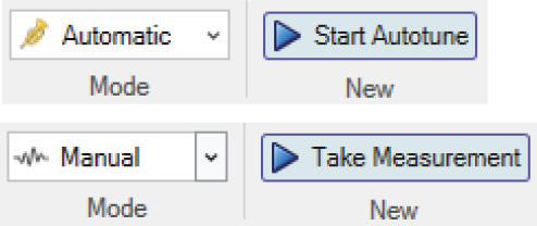
Automatic Tuning
The Automatic tuner uses default guidelines to determine tuning parameters that comply with the stability requirements.
Automatic Tuning Interface
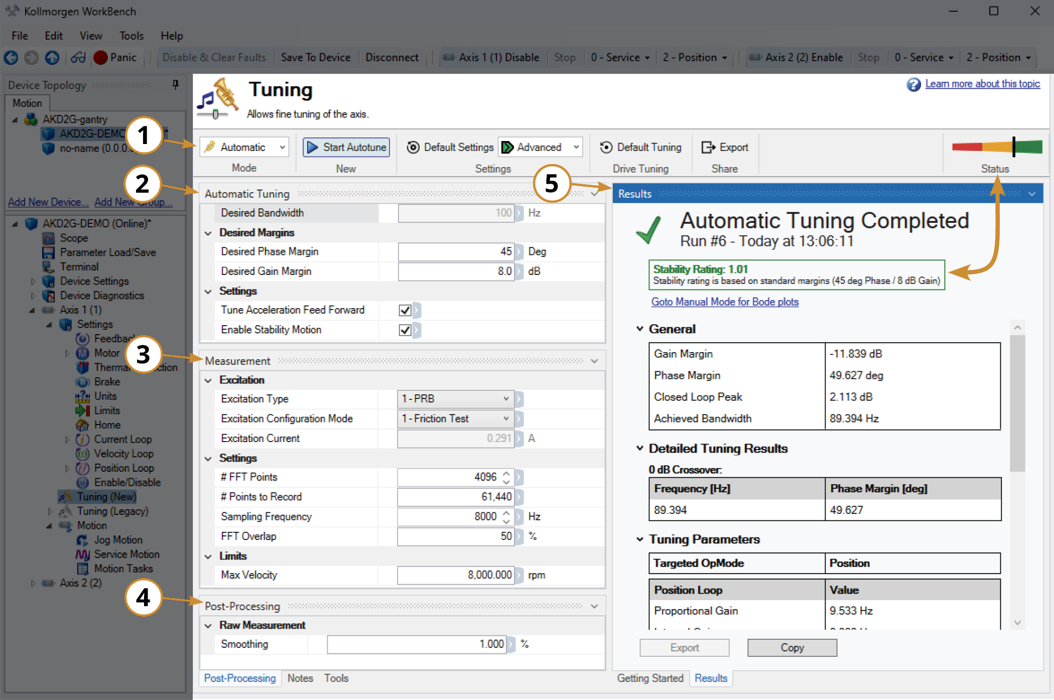
Top Ribbon
|
|
||
|---|---|---|
| Parameter | Description | |
|
Mode |
Sets the tuning method. |
|
|
New |
Start Autotune initiates the automatic tuning process. |
|
|
Settings |
Populates the Settings Pane with Basic or Advanced parameters available. The Basic setting limits the Measurement Type to Plant and Closed Loop, and limits the Settings to only # FFT Points. The Advanced setting adds Current Loop and Custom to the Measurement Type options, as well as additional FFT values to the Settings options. |
|
|
Default Settings: Resets all the editable parameters back to their default values. |
|
|
|
Drive Tuning |
Default Tuning: Resets the tuning parameters to the drive defaults at 75 Hz bandwidth. |
|
|
Share |
Export CSV files of the tuning data and parameters. |
|
|
Status |
Shows the stability rating of the Autotune results. |
|
Automatic Tuning Pane
|
Parameter |
Explanation |
|---|---|
|
Desired Bandwidth |
Defines the fixed bandwidth of 100 Hz that the Autotuner tries to achieve. This parameter is not user editable. |
|
Gain & Phase Margin |
Specifies how “hot” to tune the system. As the user lowers the margins, the Autotuner will achieve higher gains and higher system bandwidth, but stability will decrease.
|
|
Tune Acceleration FF |
When checked, the Autotuner will calculate the acceleration feed forward for the system, and write it to the drive. |
|
Enable Stability Motion |
If checked, a short move will be performed at the end of Automatic tuning and a stability algorithm verify that the control loop is stable. |
Measurement Pane
| Parameter | Options | Description |
|---|---|---|
|
Excitation Type |
1 - PRB |
Uses a pseudo random binary signal to excite the system. The signal is either positive (+) or negative (–) current or velocity amplitude (depending the injection point). |
|
2 - Sine |
Requires the start frequency, end frequency, and frequency step size be specified. The sine sweep takes significantly longer than a noise or PRB measurement but is often cleaner. Choose the step size carefully: a step size that is too large may miss important resonances, and a step size that is too small increases measurement time. |
|
|
3 - Noise |
Uses a pseudo random noise signal to excite the system. The signal varies between positive (+)/negative (-) current or velocity amplitude (depending on injection point). |
|
|
Excitation Configuration Mode |
0 - User Defined |
User sets the Excitation Current. |
|
1 - Friction Test |
The tuner will begin with a friction test to determine how much excitation is needed to acquire accurate data.The minimum current required to command continuous motion becomes the excitation current. |
|
|
Excitation Current |
Current appliedy to excite the system |
User defined, or determined from Friction Test. See Excitation Current for more information. |
|
# FFT Points |
Default value: 4096 From 1024 to 32768 |
FFT Resolution is used to generate a Bode plot from measured data. |
|
# Points to Record |
Determined by the # FFT Points chosen by default |
Total number of sampled data points. |
|
Sampling Frequency |
Default 8000, Range: 500, 1000, 2000, 4000, and 8000 |
Rate at which the points are sampled. |
|
FFT Overlap |
Percentage |
Percentage of overlap of time blocks |
|
Max Velocity |
Sets AKD2G:AXIS#.VL.THRESH or AKD:VL.THRESH to a maximum velocity for the excitation tests. If the excitation causes the motor to exceed this value, a Motor Overspeed fault is thrown. |
|
Post-Processing
Raw Measurement Smoothing smooths noisy or low-resolution data. See Post Processing Smoothing %.
Tuning Results Pane
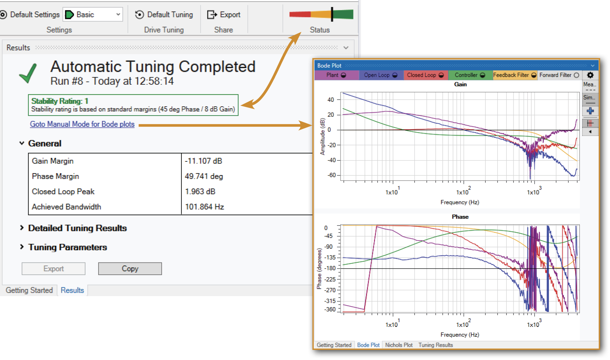
The Results pane provides the general and detailed tuning results, along with the tuning parameters values used. The results can be copied and pasted in any text editor.
View the resultant Bode and Nichols plots by clicking the link in the Results pane, or switching to Manual mode.
Automatic Tuning Procedure
The Autotuner uses default guidelines to determine tuning parameters that comply with stability requirements.
The Autotuner will tune the system using the following settings:
The Autotuner will tune the system using the following settings:
-
Position Loop Proportional (PL.KP)
-
Velocity Loop Proportional (VL.KP)
-
Anti Resonance Filter 1 Set to Lead Lag (AR1)
-
Anti Resonance Filter 3 (AR3) & 4 (AR4) set to Lowpass
-
These are set to reduce audible noise.
-
-
- These settings cannot be changed and will always be tuned.
To Get Started:
-
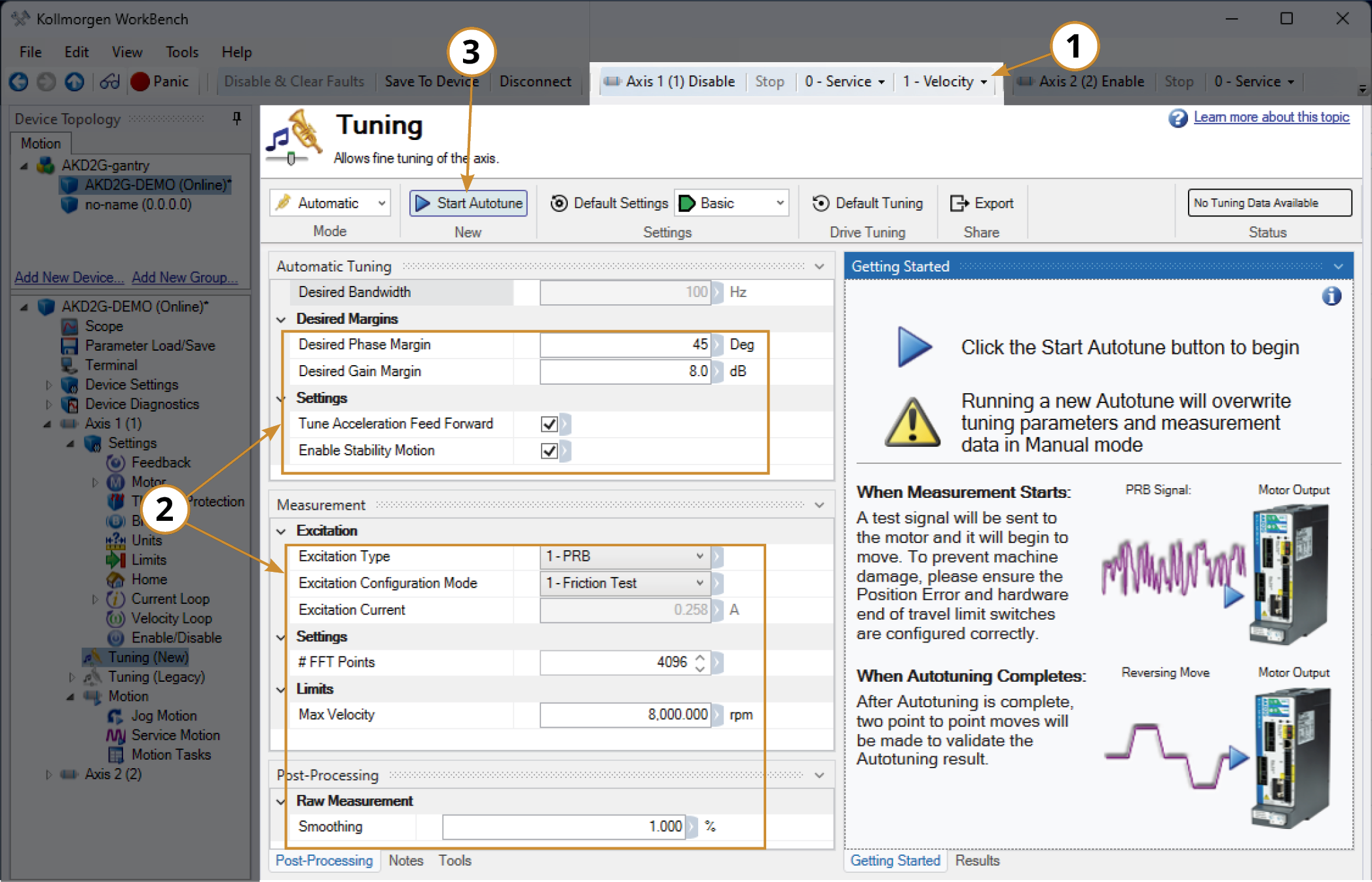
Put the drive in Velocity or Position mode depending on how the axis will be operated.
-
Adjust any user-definable as desired.
-
Start Autotune.
Results
Once the Autotuner finishes, the Status and Results pane will appear. The Status is a visual representation of the Stability Rating shown in the Results pane.

The Results pane provides the general and detailed tuning results, along with the values of the tuning parameters used. The results can be copied and pasted in any text editor.
View the resultant Bode and Nichols plots by clicking the link in the Results pane, or switching to Manual mode.


