Using Simulation to Tune the System
Instabilities can be frustrating, noisy, and damage equipment. Simulating tuning allows the tuner to accurately predict stability and performance without enabling the motor and making test moves!

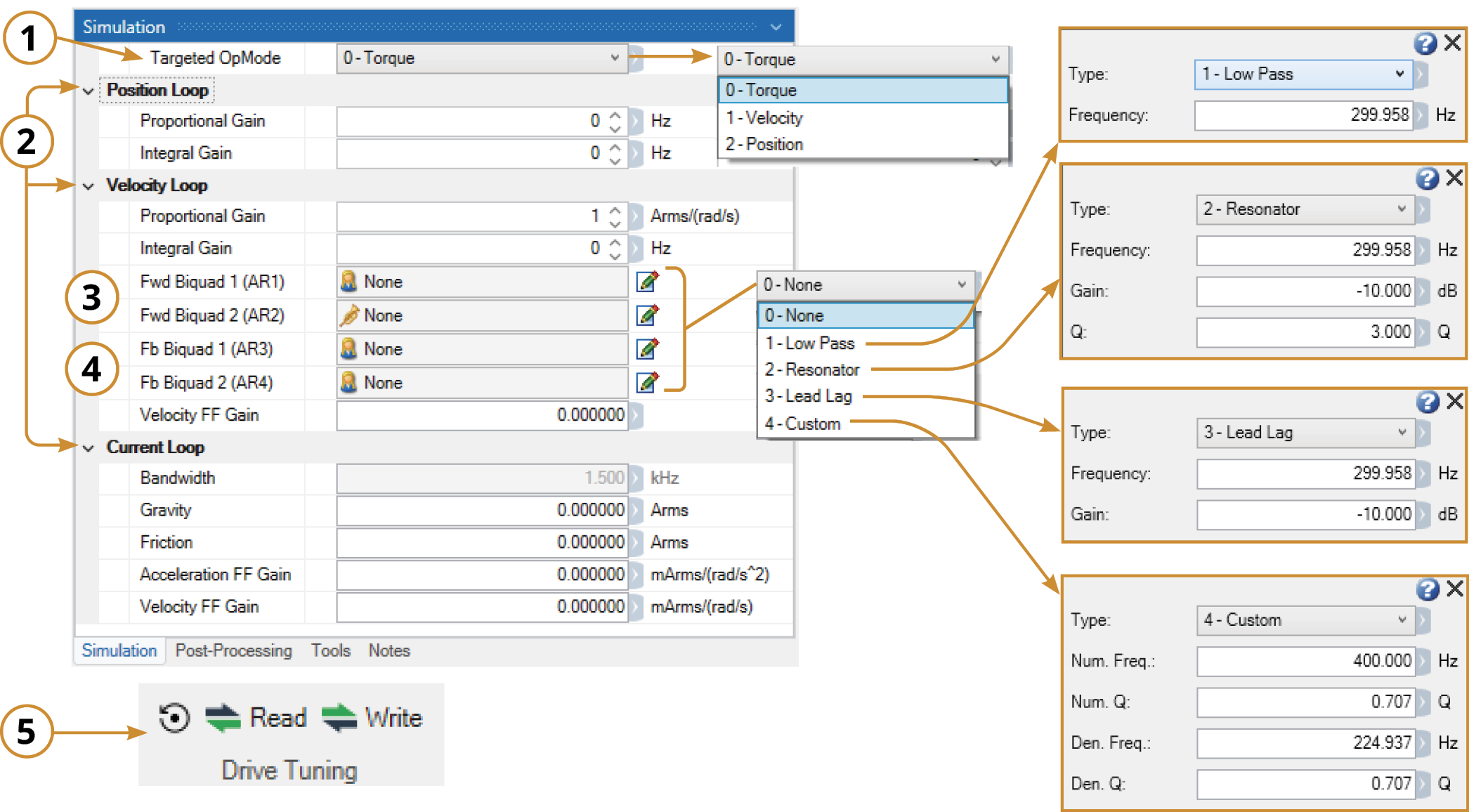
Within the Simulation Tab, there are several groups:
-
Targeted OpMode: Select between Torque, Velocity, Position modes
This Setting chooses which loop to simulate – This should normally be set to Position
-
Loop Gains: Contains all VL.XX and PL.XX tuning parameters as well as feed forwards
-
Forward Filters: AR Filters 1 & 2
-
Feedback Filters: AR Filters 3 & 4
-
Read/Write (in the ribbon bar) restore drive tuning into the simulation window or write current simulated tuning to the drive.
How to Simulate Tuning:
-
After measurement completes, disable the drive
-
Click on the Simulation Tab
-
Evaluate the bode plot for stability issues and poor low-frequency results
-
Change the Targeted OpMode to Velocity, or Position Loop depending on which your system will use and adjust the parameters to achieve stability and the desired bandwidth.
Review the how each of the parameters affects tuning via the links below. Start with adjusting the Feed Forwards, then Gains, and finally Filters. -
As each parameter is adjusted, evaluate its effect on the bode plot, stability rating, and if it helps move the system closer to the desired bandwidth.
-
Review the Tuning Fundamentals section to see how each parameter affects the response.


