Project Explorer
This window contains all the items used to design, implement, test, and document the application.
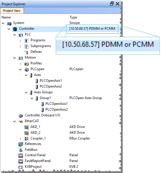
Figure 1: KAS Project Explorer
|
Item |
Description |
|---|---|
|
Hardware |
Devices that make up the system such as Controllers, EtherCAT Motion Bus, servo and stepper drives, HMI devices, I/O Terminals, etc. |
|
Motion |
|
|
PLC (IEC 61131-3) |
|
-
-
Navigate in the project-tree by entering the item's initial letter or using the arrow keys.
A project is made of these items:
-
-
Node Names: Allowable characters for node names include A-Z, a-z, 0-9, . (period), - (hyphen), and _ (underscore).
System
This item concerns the whole project. A right-click opens its menu that provides these options:
|
Command |
Description |
|---|---|
|
Add HMI Device |
Add a new HMI device with a KVB panel. See HMI Device. |
Controller
A controller is composed of:
- a PLC item
- a Motion item
- a Control Panel
- an EtherCAT Motion Bus
- some References
This item displays the controller's IP address and controller hardware type.
- It is used to Access the Web server From the KAS-IDE.
- The webserver functionality may be used directly in the KAS-IDE.
- See Using the KAS Web server.
-
-
The IP address is shown as
127.0.0.1if the system is in simulation mode.
Controller Node - Context Menu
|
Command |
Description |
|---|---|
|
Add Control Panel |
Add a new control panel to the controller. See Control Panel. |
|
Import Control Panel |
Import a pre-configured control panel for use in the project. |
|
Add KVB Project |
Add a new KVB panel which is embedded into the controller. See KVB Project. |
|
Import KVB Project |
|
|
Add a node to the tree to access a SafePLC2 project directly from the KAS-IDE. See SafePLC2 Projects. |
|
|
Import SafePLC2 Project |
Select a
|
|
Add Fieldbus |
Add a node to access the Fieldbus Editor. |
|
Access Web Server |
This command opens the web server interface in the GUI. See Access the Web server From the KAS-IDE and Using the KAS Web server. |
|
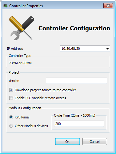
Properties |
Open a dialog box to configure the controller.
Figure 2: Configure the Device Parameters Description
|

PLC
This item contains all the PLC (Virtual Machine) part of the controller.
These items can be present in the PLC:
- Programs
- Subprograms
- Some Defines
|
Command |
Description |
|---|---|
|
Libraries |
Import new libraries |
Programs
|
Command |
Description |
|---|---|
|
Cycle |
Configure the cycle of the virtual machine. See Define the PLC Cycle. |
|
Import a saved program. |
|
|
New Program |
Add new program items: |
-
-
Programs and Subprograms can be reordered by drag-and-drop.
Dragging an item up the list places it above the program you drop it on, while dragging down places it below.
Program Item - Contextual Menu
|
Command |
Description |
|---|---|
|
Add Child SFC |
Add a child program to this program.
|
|
Import Child SFC |
Import a saved SFC program to the current program.
Only local variables are copied (not the global variables). |
|
Save the selected program to your file server, avoiding spaces in the file name. |
|
|
Rename |
Rename the selected program. |
|
Delete |
Delete the selected program. |
|
Print SFC and All Level 2 |
Print all PLC programs. See Print. |
-
-
Double-click the program name to open the program in the workspace.
Subprograms
|
Command |
Description |
|---|---|
|
New Function (Subprogram) |
Add a new subprogram item: |
|
New UDFB |
Add a new UDFB item: |
|
Import |
Import a saved program. |
Subprogram Item - Context Menu
You can create your own functions as well as functional blocks that are called UDFBs (User-Defined Functional Blocks).
For each of them, use these commands:
|
Command |
Description |
|---|---|
|
Export |
Save the selected subprogram onto your file server. |
|
Rename |
Rename the selected subprogram. |
|
Create Unlocked Copy |
Duplicate the selected, locked subprogram. The duplicate is NOT locked. |
|
Delete |
Delete the selected subprogram. |
|
In/Out Parameters |
Open the Program Properties dialog box to Declare Functions or Function Blocks. This item is disabled for locked UDFBs. |
-
-
Double-click the subprogram name to open the subprogram in the workspace.
Defines
This item contains all the global definitions in the scope of the corresponding device.
See also see "Use the Defines List" on page 1.
-
-
Double-click a Define item to show these global definitions.
A file of internal defines are found in the installation directory of the KAS-IDE\Astrolabe\Bin\HwDef\lib.eqv.
Motion
The motion item contains the motion-specific items (e.g., the Profiles and Pipe Network items).
|
Command |
Description |
|---|---|
|
Motion Engines |
Choose the motion engine for the application Pipe Network or PLCopen. |
Profiles
This item contains all the cam profiles in the project.
|
Command |
Description |
|---|---|
|
New Profile |
Create a new cam profile and add it to this device (*.csv, *.cam). See Adding Cam Profiles. |
|
Import |
Import already existing cam profiles to a project. |
|
Show Compiled Code |
Show the code corresponding to the selected cam profile. |
Right-click a cam profile to use these additional commands:
|
Command |
Description |
|---|---|
|
Rename |
Change the cam profile to a different name. |
|
Delete |
Remove the cam profile from the list. |
|
Export |
Save the cam profile in (.CAM) format. |
|
Properties |
Opens a dialog to modify the cam profile's Master/Input Slave/Output Offset and Scale values. |
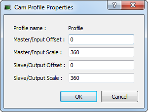
See Adding Cam Profiles and Cam Profile Editor.
Pipe Network
This menu applies to the Pipe Network in the project.
|
Command |
Description |
|---|---|
|
Import and Replace |
This command replaces the existing Pipe Network with a pre-saved Pipe Network. A dialog box opens to locate the pre-saved file. The Pipe Network Editor is opened when the file is imported. |
|
Export |
Export the Pipe Network to a file for reuse. |
|
Show Compiled Code |
Show the code corresponding to the Pipe Network. |
-
-
The existing EtherCAT axis mapping is lost when using Import and replace.
Profiles assigned to Cam blocks are cleared.- In the Project View, double-click EtherCAT to open the EtherCAT Devices tab.
- Use the tab to reassign the axes.
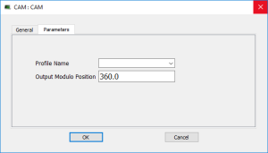
- Double-click any cam of the blocks and set the Profile_Name parameter.
-
-
Double-click to open the Pipe Network in the workspace.
PLCopen
|
Command |
Description |
|---|---|
|
New Axis |
Add a new axis to your project. |
|
Show Compiled Code |
Show the code corresponding to the PLCopen. |
Axes
- Each axis is listed here, whether it is found via a scan of the EtherCAT network, or added manually.
- To add an axis manually, right-click and select New Axis.
For each PLCopen axis, use these commands:
|
Command |
Description |
|---|---|
|
Properties |
Open a dialog box to Modify PLCopen Axis. |
|
Delete |
Delete the selected axis. |
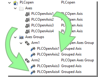
Axes Groups
Axes Groups are collections of related axes defined by the data type AXIS_GROUP_REF.
- They are typically used by coordinated motion and function blocks such as MC_SetKinTra.
- Right-click in this section to create a new Axes Group.
- Groups are populated by dragging an existing axis from the above section into the group.
These commands are available by right-clicking on a group.
|
Command |
Description |
|---|---|
|
Delete |
Delete the selected Axes Group. |
|
Rename |
Change the name of the Axes Group. |
Control Panel
This holds the Control Panel item used to provide a basic interface between you and the virtual machine.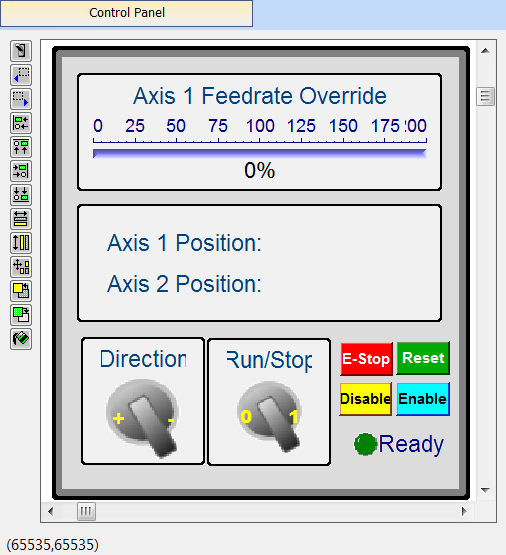
- See Design the HMI with the Internal Editor.
- See KVB Project for a more advanced tool to build HMI.
|
Command |
Description |
|---|---|
|
Rename |
Rename the selected Control panel. |
|
Delete |
Delete the selected Control panel. |
|
Export |
Export the control panel for use in other projects. |
-
-
Double-click to open the Control Panel in the workspace.
Controller Onboard I/O
|
Command |
Description |
|---|---|
|
Properties |
Open the Properties dialog box to configure the local I/O for the AKD PDMM or PCMM controller. |
EtherCAT
This item gives access to all the devices linked to the EtherCAT Motion Bus.
|
Command |
Description |
|---|---|
|
Add Device… |
In the Project view, add a Kollmorgen drive, power supply, or coupler, per a third-party EtherCAT device to the EtherCAT node. |
|
Scan Devices |
TheKAS Runtime sends EtherCAT messages to discover the devices present in the network. See EtherCAT Devices tab. |
|
Enable/Disable Online Configuration Mode |
Toggles Online Configuration Mode on and off. |
|
Properties |
Opens the Properties dialog box. |
See Add and Configure Third Party Devices.
AKD2G Drive
Double-click an AKD2G to set its parameters.
See Configure the AKD / AKD2G Drive.
|
Command |
Description |
|---|---|
|
Rename |
Rename the selected drive. |
|
Delete |
Delete the selected drive. |
|
Configuration |
Opens the Configuration tab for the AKD GUI. |
|
Properties |
Select the Properties menu to access the EtherCAT device's configuration views. |
AKD Drive
Double-click an AKD to set its parameters.
See Configure the AKD / AKD2G Drive.
|
Command |
Description |
|---|---|
|
Rename |
Rename the selected drive. |
|
Delete |
Delete the selected drive. |
|
Configuration |
Opens the Configuration tab for the AKD GUI. |
|
Properties |
Select the Properties menu to access the EtherCAT device's configuration views. |
AKD-C Central Power Supply
Double-click an AKD-C to set its parameters.
See Configure the AKD / AKD2G Drive.
|
Command |
Description |
|---|---|
|
Rename |
Rename the selected device. |
|
Delete |
Delete the selected device. |
|
Properties |
Select the Properties menu to access the EtherCAT device's configuration views. |
|
Configuration |
Opens the Configuration tab for the AKD GUI. |
AKD-N Drive
Double-click an AKD-N to set its parameters.
See Configure the AKD / AKD2G Drive.
|
Command |
Description |
|---|---|
|
Rename |
Rename the selected drive. |
|
Delete |
Delete the selected drive. |
|
Properties |
Select the Properties menu to access the EtherCAT device's configuration views. |
|
Configuration |
Opens the Configuration tab for the AKD GUI. |
AKT (K-Bus) I/O Coupler
The Standard I/O Coupler node gives access to its I/O slices.
|
Command |
Description |
|---|---|
|
Add I/O Slice |
Add a new slice (Digital or Analog Input and Output) to the selected Standard I/O Coupler. |
|
Rename |
Rename the selected coupler. |
|
Delete |
Delete the selected coupler. |
|
Properties |
Select the Properties menu to access the EtherCAT device's configuration views. |
-
- These commands are disabled when the controller is running.
See Troubleshooting about diagnosing the coupler LEDs.
AKT2G (EtherCAT) I/O Coupler
The Coupler node acts as a gateway for E-Bus I/O slices.
|
Command |
Description |
|---|---|
|
Rename |
Rename the selected coupler. |
|
Delete |
Delete the selected coupler. |
|
Properties |
Select the Properties menu to access the EtherCAT device's configuration views. |
-
- These commands are disabled when the controller is running.
See Remote Input/Output Terminals.
I/O Slice
- AKT (K-Bus) slices are children of the AKT I/O Coupler.
- AKT2G (E-Bus) slices are children of the EtherCAT node.
|
Command |
Description |
|---|---|
|
Rename |
Rename the selected slice. |
|
Delete |
Delete the selected slice. |
|
Properties |
Open the Properties dialog box to configure the I/O slice. |
Device
Double-click a Device to access its EtherCAT device configuration views.
|
Command |
Description |
|---|---|
|
Rename |
Rename the selected device |
|
Delete |
Delete the selected device |
|
Add Module… |
Add a module to an MDP device. |
|
Properties |
Access the EtherCAT device's configuration views. |
Module
|
Command |
Description |
|---|---|
|
Rename |
Rename the selected module. |
|
Delete |
Delete the selected module. |
References
Used to insert references into a project.
Each reference is a user-defined reference that links any kind of deliverable to your project.
|
Command |
Description |
|---|---|
|
Insert Reference |
Link any kind of deliverable to your current project. |
|
Delete |
Delete the reference. |
|
Properties |
Open the referenced file in the workspace. |
-
-
Double-click to open the Reference in the workspace.
Fieldbus
This item holds the Fieldbus Editor to configure the Ethernet/IP or Profinet fieldbuses.
See Fieldbus Editor.
HMI Device
This item holds the HMI (Human Machine Interface) item used to provide an advanced interface between you and the virtual machine.
|
Command |
Description |
|---|---|
|
Add KVB Project |
Add a new KVB panel to the controller. See HMI. See Add an HMI Device for mode details. This command is disabled when a KVB panel already exists. |
|
Import KVB Project |
|
|
Rename |
Rename the selected HMI device. |
|
Delete |
Delete the selected HMI device. |
KVB Project
|
Command |
Description |
|---|---|
|
Open KVB |
Opens the associated KVB project. |
|
Rename |
Rename the selected KVB panel. |
|
Delete |
Delete the selected KVB panel. |
|
Export |
Save a copy of the panel in a compressed (.ZIP) file. |
-
-
Double-click the entry to open the KVB panel in Kollmorgen Visualization Builder
SafePLC2 Project
|
Command |
Description |
|---|---|
|
Delete |
Delete the SafePLC2 project. |
|
Export |
Select a location and name to export / create a SafePLC2 file. |
|
Open SafePLC2 |
Creates or opens a synchronized SafePLC2 project. See SafePLC2 Projects. |
|
Rename |
Rename the SafePLC2 project. |
-
-
Double-click the entry to open SafePLC2.


